光技術情報誌「ライトエッジ」No.35(2011年8月発行)
2011.3 SPIE Advanced Lithography 2011
Development of debris-mitigation tool
for HVM DPP source
Hironobu Yabuta, Shinsuke Mori, Takahiro Inoue, Yusuke Teramoto, Hiroto Sato, Kazuaki Hotta
Gotemba R&D Center, Extreme Ultraviolet Lithography System Development Association (EUVA),
1-90 Komakado, Gotemba, 412-0038 Shizuoka, Japan
ABSTRACT
Debris-mitigation tools (DMTs) have been used in DPP sources and the performance has been well proven in alpha sources. In beta and HVM sources, requirement to the DMT is increasing to fulfill the power and lifetime requirements simultaneously. In order to bring DPP technology into HVM level, a high-performance DMT has been developed. It high mitigation performance for both neutral and ionic debris, large collection angle of the collector having high optical transmission, and withstand large thermal input from the discharge source head. Experiments were carried out using mirror samples and proved sufficient performance with which no sputtering and deposition were observed.
Keywords: EUV, debris-mitigation, DMT, DPP
1. INTRODUCTION
HVM source has been developed for EUV lithography. To deliver EUV from pinch to IF without a degradation of collector, high performance DMTs are also needed. From tin DPP source, nano-size particles (ion, neutral particle, molecular) and over micron-size particles (grain etc.) are emitted. A reflective coating of collector are sputtered by fast/small size particles like ion, neutral etc. When slow/large size particles like tin grain, cluster etc. are deposited on the coating surface, they will absorb EUV. Finally, a reflectivity of the collector is degraded due to both effects. To protect the collector from the degradation, we have been also developed such DMTs for tin DPP SoCoMo. In this work, we evaluated DMT performance and optimized some operating condition and structure using test stand system.
Meanwhile SoCoMo and scanner have been coupled directly in EUVL. There is the pressure difference between SoCoMo and scanner because a buffer gas for the mitigation of the collector is used in SoCoMo. Then, not only the gas but also the contamination will come together. A long lifetime of masks and mirrors are really required in the HVM EUVL tool. Hence, the degradation of these mirrors by debris and contamination from SoCoMo is a serious issue. The contamination from source has not been researched yet. To investigate this issue, an evaluation tool of the mirror degradation was developed [1]. In this work, to prove cleanliness behind IF, the sample exposure chamber system and the evaluation tool were used with tin DPP SoCoMo
2. EVALUATION AND OPTIMIZATION OF DMT PERFORMANCE
Figure 1 shows a setup of test stand for DMT development. Tin DPP source was connected to the test stand. TMPs were also installed and evacuated a buffer gas to be the same chamber pressure for SoCoMo. Total pumping speed was smaller than that of SoCoMo. Therefore, the buffer gas flow rate was also small. A special sample holder was installed to this test stand. The sample positions were corresponding to actual collector shell surface of SoCoMo. Sample piece was about 1cm2 of a ruthenium coated silicon plate. In each condition, discharge pulses were about 100 Mshots.
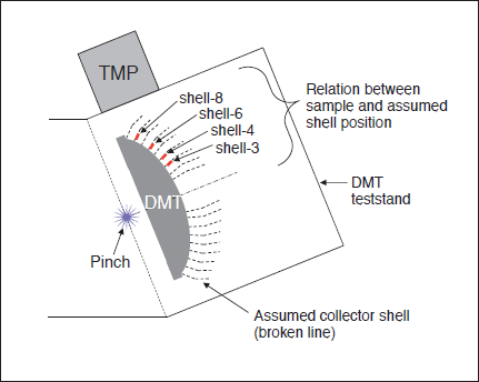
Fig.1: Schematic diagram of DMT test stand and sample positions.
To evaluate the sample before and after experiment, X-ray fluorescence analysis (XRF) was used to determine an average thickness of ruthenium and tin on sample. The results are shown in Figs 2 to 4. A vertical axis of the graph is shown the thickness. For example, when that takes a plus (positive) value, it means that tin is deposited on sample. When that takes a minus (negative) value, it means that ruthenium coating is sputtered on sample.
Figure 2 shows XRF measurement result for 1st setup. With this condition, tin depositions of each shell position were larger than ruthenium sputtering. For 1 nm tin deposition, a normalized EUV reflectivity of ruthenium coating will be going down more than 10% [2]. Then it is impossible to keep the performance for the collector optics.
To improve it, the buffer gas flow was changed for 2nd setup. The result is shown in Fig. 3. With this improvement, an average tin deposition could be reduced by about 10 % from 1st setup. However, tin deposition was still higher than ruthenium sputtering. Hence in Fig. 3, values for each shell are pointed out. When the buffer gas flow was changed, tin depositions for outer shell were mainly improved. Therefore, samples for the outer shell would be strongly affected by the gas flow into the chamber. As shown in Fig. 1, the buffer gas flow and debris flow included a vaporized tin at pinch might be evacuated by TMPs around DMT.
For 3rd setup, we considered and improved the effect of gas flow path. The result is shown in Fig. 4. Tin deposition was much less than that of 1st and 2nd setup. And it was also less than ruthenium sputtering. For example, if we have l micron of ruthenium coating thickness, then sufficient reflective layer is remained after a few hundred Gshots. Hence, the values of ruthenium sputtering were pointed out. They werenʼt changed for all setup. Moreover, the values of inner shell had higher than that of the outer shell. It is clear that ruthenium sputtering is not strongly affected by the gas flow.
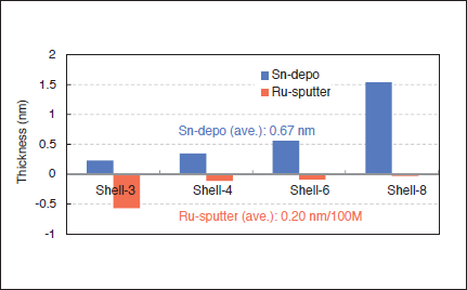
Fig.2 : XRF measuremen t result for 1st setup.
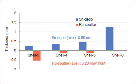
Fig. 3 : XRF measurement result for 2nd setup.
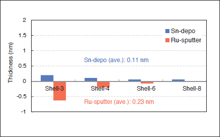
Fig. 4 : XRF measurement result for 3rd setup.
Probably, the sputtering is affected by some configuration and structure inside DMT. Therefore, a gas flow control around outer shells and a configuration and structure around inner shells will be necessary to upgrade DMT performance
The sample surface was analyzed by SEM. Figure 5 shows two representative regions after about 100 Mshots (3rd setup). The sample was a ruthenium coated silicone plate. The small dark and bright region of these SEM image were the columnar structure of ruthenium at the top surface. They can also see a sample before experiment. Although some tin deposition and ruthenium sputtering could be found by XRF, there were no significant changes between before and after the experiment with SEM analysis.
The surface roughness was measured by AFM. And EUV reflectivity was measured by a reflectometer with xenon EUV source. Figure 6 shows them for the sample of 3rd setup. The measured roughness was 0.3 nm. And it had no significant change compared before experiment. Also EUV reflectivity had no change. Therefore, there was no influence caused by ruthenium sputtering.
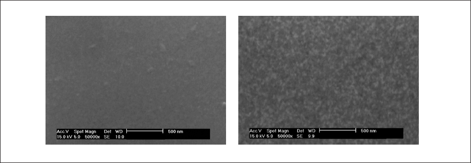
Fig. 5: SEM images after experiment for 3rd setup.
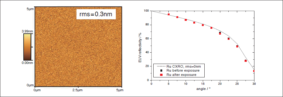
Fig. 6: Surface roughness and EUV reflectivity for 3rd setup.
3. EVALUATION OF CLEANLINESS BEHIND IF
A clean photon is required for SoCoMo to connect a scanner. Because SoCoMo and scanner have been coupleddi rectly in EUVL. An experimental setup as shown in Fig. 7 was used to evaluate contaminations from SoCoMo. A sample which was a multilayer Mo/Si mirror piece was installed at 100 mm or 200 mm behind IF to expose with EUV radiation. To avoid an overheating of sample by the radiation, the sample holder was cooled by coolant circulation from the atmosphere side. With this cooling system, its surface temperature would be kept less than 60 °C. A sample exposure chamber was attached behind IF and it was evacuated by TMP. Then the exposure chamber pressure was around 10-3 Pa. EUV reflectivity and X-ray photoelectron spectroscopy (XPS) were used to evaluate contaminations on the sample. It is known that mirror optics is degraded by oxide and/or carbon for a scanner side. In the atmosphere, a lot of oxygen and carbon are existed. To measure the only deposited oxide and carbon in the chamber, the sample should be handled without breaking vacuum. For this experiment, we developed and used a quasi in-situ measurement system to detect them [1]. Figure 8 shows the schematics of our measurement system.
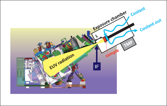
Fig. 7: Experimental setup for cleanliness measurement behind IF.
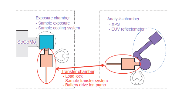
Fig. 8: Schematic diagram of quasi in-situ sample measurement system.
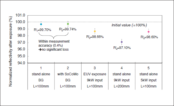
Fig. 9 : EUV reflectivity after experiment.
Experimental results are shown in Fig. 9. A vertical axis is a normalized reflectivity. For each experiment, an initial reflectivity was defined to 100%. And a horizontal axis is an experiment number and condition. 1st and 2nd experiments were measured for each background without EUV condition. For background measurements, there was no significant loss. 3rd to 5th experiments were measured with EUV radiation. In these cases, the reflectivity was dropped a little. After exposure, oxygen and carbon peak intensity of XPS were also changed. Therefore, the reflectivity loss is caused by the deposition of carbon and/or oxide. This phenomenon is well - known degradation me chanism for multilayer mirror that are exposed to EUV. For 3 different exposure conditions, the reflectivity was also different. It would be due to some complicate effects which are distribution of contamination in the exposure chamber, intensity of radiation from pinch, a sputtering of EUV driven plasma etc. To explain them, we will need more investigations. However, note that the mirrors will be protected against these phenomena in a real EUV scanner, which are mentioned into some patents etc. [3, 4]
Typical XPS spectrum after EUV exposure is shown in Fig. 10. If there was a tin, then it should have a peak around 485- 487 eV. In the all measurement, we couldnʼt see any tin peaks. And the depth profile of the exposed sample was also measured with XPS. Then there was no tin peak. Hence, tin from pinch is completely blocked in DPP-SoCoMo and there is no tin behind IF.
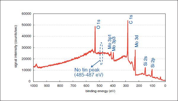
Fig. 10: XPS survey spectrum after 4th experiment.
4. CONCLUSIONS
DMT performance was evaluatedwith test stand. After some optimization, we could obtain small tin deposition and ruthenium sputtering. And SEM image had no difference after 100 Mshots. A sur face roughnes s and EUV reflectivity also had no significant deterioration. In conclusion, DMT is working well for tin debris. Additionally cleanliness behind IF was evaluated with a quasi in-situ sample measurement system. No tin peak was detected. This means tin is completely blocked in tin DPP SoCoMo and a clean photon can be delivered to a scanner.
ACKNOWLEDGEMENTS
We would like to thank XTREME technologies GmbH for many useful discussions and advices. This work has been supported by New Energy and Industrial Technology Development Organization (NEDO).