Technical Support Information (Laser)
Ushio provides technical information to help customer's better understanding of the products. You can access the principle of laser diode operation, symbol and technical word definition used in data sheet and in brocher, and caution for handling.
Also please refer to FAQ list.
Technical Support Information (Laser)
Laser Diodes Structures
1. GaAlAs LD Structure
The p-type active layer, in which stimulated emission enforces optical amplification (figure 1 (a)), is processed first. The p-n junction is made here for injecting minority carriers (the p-n hetero junction). With forward current applied to the junction, electrons in n-type region are injected into p-type region. With a p-type semiconductor of wide band gap on the other side of the p-n junction (hetero isolation junction), the injected carriers are mostly confined within the p-type active layer. This carrier confinement makes population inversion occur easily, increasing the light emission intensity.
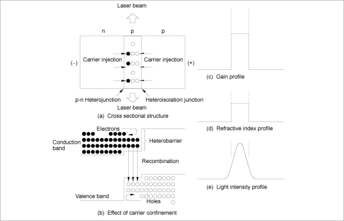
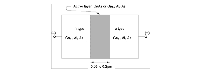
The active layer of the GaAlAs LD is made of GaAs or Ga1-yAlyAs (figure 2). The thickness of the layer is approximately 0.05 to 0.2mm. P-type(Ga1-xAlxAs) and n-type(Ga1-xAlxAs) (x>y) sandwich the active layer (x and y here are the mixture ratio of Aluminum). When x is 0.3, the band gap of the sandwich layers is 1.8 eV, and there is a balance of 0.4 eV against 1.4 eV of GaAs active layer. When forward bias is applied here, the hetero barrier confines carriers within the 0.05 to 0.2mm active layer, carrier population is inverted and the gain increases. The refractive index of the GaAs is higher by some percent than those of Ga1-xAlxAs, which confines the generated light within the GaAs active layer. The light penetrating into the AlxAs layer is not absorbed because of its wide band gap. So laser oscillates effectively there (figure 1). A thinner active layer (called multiple quantum well structure) can make do with less threshold current density to achieve laser oscillation. At present, a threshold current density of as low as 1 to 2 kA/cm2 can be achieved, realizing a stable continuous oscillation (CW) at room temperature.
2. LD Lasing Modes
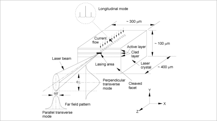
Under laser oscillation, a light standing wave created with its wave front parallel to the mirror facets while light is traveling back and forth within the laser cavity. This standing wave consists of a longitudinal mode and a transverse mode (figure 3). The longitudinal mode expresses the condition of the standing wave in the direction of cavity length (z direction). The transverse mode expresses the condition of the axis perpendicular to the cavity length direction. The transverse mode is divided into a perpendicular transverse mode which is perpendicular to the active layer, and a parallel transverse mode which is parallel to the layer.
2.1 Longitudinal Mode
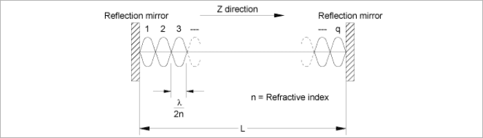
Figure 4 shows that a half-wavelength standing wave multiplied by an integer, q, forms in the direction of the laser cavity length (z direction). When the refractive index of the medium is n and the wavelength in a vacuum is λ, the wavelength of light λ0 in the medium is expressed as:
λ0 = λ / n
So the half wavelength is expressed as:

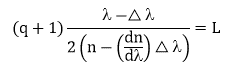
As described above, the half wavelength multiplied by an integer, q, equals to the cavity length, L:

Since a cavity length is incomparably longer than a wavelength, cavity resonance can take place at multiple wavelengths. The particular wavelength in which the cavity gain becomes maximum will then produce a stable standing wave.
The longitudinal mode which q is increased by 1 is expressed as, in consideration of the wavelength dispersion of the refractive index.
△λ: Wavelength change
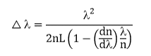
Since q is big enough, the wavelength change is expressed as:
In a semiconductor laser diode, when the temperature changes, the band gap energy changes causing the wavelength where the maximum gain is achieved to change. As for the GaAlAs DH structure laser, this temperature coefficient is about 0.20 nm/°C. The same phenomenon takes place because of temperature rise in the active layer when the injection current increases to achieve higher optical output power under continuous operation (CW).
2.2 Perpendicular Transverse Mode
In a GaAlAs laser diode, the active layer is sandwiched by hetero junctions (figure 5). Light is confined within the active layer because of the higher refractive index inside the layer than that of the outer GaAlAs layers. The amount of light confined within the active layer depends on its thickness. A thicker layer confines more light. Also, light penetrates into the outer layers when the active layer is too thin. The width of laser beam divergence depends on the thickness of the active layer, and when it is 0.3 to 0.4 µm, the width becomes narrowest. At this width, the radiation angle of laser beam emitted from the cleaved facet becomes widest (figure 6). In general, in a semiconductor laser, the radiation angle of the laser beam becomes very wide because the laser beam profile width in the device is the same as or less than the lasing wavelength. This is very different from what occurs in a conventional gas laser or solid state laser.


2.3 Parallel Transverse Mode
A waveguide must be formed by some means because there is nothing to guide light in the active layer in a direction parallel to the junction. When current injection is limited to a narrow enough region with a full cavity length, laser oscillation can then take place in the region (figure 3). Figure 7 shows the basic stripe structure which can limit current pass only.
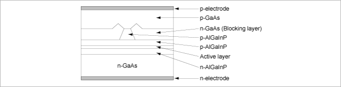
In order to control the transverse mode more effectively, the refractive index profile or the optical loss profile should also be built into the stripe structure. Figure 8 shows examples of this structure.
Figure 8 describes a ridge laser. The light penetrated from the active layer is absorbed in the blocking layer. Therefore, the refractive index profile is built into the stripe area.
These structural waveguides stabilize the single fundamental transverse mode.