Technical Support Information (Laser)
Ushio provides technical information to help customer's better understanding of the products. You can access the principle of laser diode operation, symbol and technical word definition used in data sheet and in brocher, and caution for handling.
Also please refer to FAQ list.
Technical Support Information (Laser)
Symbols and Definitions
1. The Absolute Maximum Ratings
The absolute maximum ratings specified in each data sheets are the values which should not be exceeded under any condition. They are defined at the case temperature, TC, of 25°C unless otherwise specified. However, individual specification prescribes the temperature dependency of the characteristic.
The absolute maximum ratings of laser diodes are defined individually as follows.
Table 1 Absolute Maximum Ratings
| Item | Definitions |
|---|---|
| Optical output power, Po, Po (pulse) |
Maximum tolerable output power under continuous wave (CW) or pulsed whatever specified operation. |
| Reverse voltage, V R |
Maximum tolerable reverse bias voltage applied to a device. For the LDs with a built-in photodiode, the reverse voltages of the photodiode, VR(PD), and of the LD, VR(LD), are specified respectively. |
| Operating temperature, Topr |
Operating temperature is defined by the value of the case temperature of a device. This value also differs according to product type. |
| Storage temperature, Tstg |
Ambient temperature range under which a device can be safely stored. This value differs according to product type. |
2. Optical and Electrical Characteristics
The limit values and the typical values of optical and electrical characteristics are described in each data sheets as much as possible for the user’s convenience for application to electrical circuits and optics.
The definitions of optical and electrical characteristics are listed below.
Table 2 LD Optical and Electrical Characteristics
| Item | Definitions |
|---|---|
| Optical output power, Po, Po(pulse) |
Optical output power under the specified forward current, IF . |
| Threshold current, Ith | Forward current at which a diode starts to laser (figure 1). Practically, this value is specified as the crossing point of x axis and the extension of line B, where “A” is spontaneous emission region and “B” lasing region. |
| Operating current, Iop | Forward current under the specified optical output power. |
| Operating voltage, Vop | Forward voltage under the specified optical output power. |
| Slope efficiency, ηs | Optical output power increment per unit drive current in lasing region (B region) of figure 1. |
| Droop, –Rth | Droop is defined as the variation of the optical output power between two duty cycles at 600 Hz. It is calculated by the formula as below; where P0 is the initial power at the duty cycle of 10% and P1 is the end power at the duty cycle of 90% (figure 2). 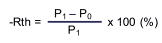
|
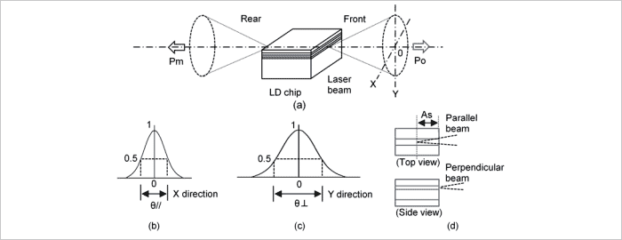
| Beam divergence parallel to the junction, θ// Beam divergence perpendicular to the junction, θ⊥ Astigmatism, As |
Divergence of light beam emitted from a laser diode is described in figure 3 (a). θ// is the full angle at a half of the peak intensity in the parallel profile (figure 3 (b)). θ⊥ is the full angle at a half of the peak intensity in the perpendicular profile (figure 3 (c)). |
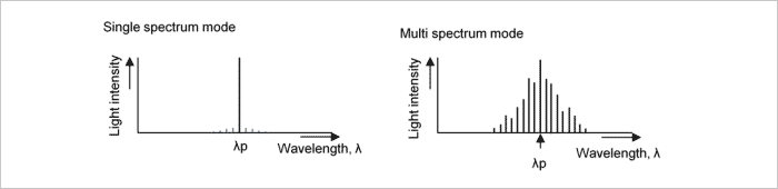
| Lasing wavelength, λp | Maximum intensity wavelength in a spectral distribution (figure 4). |
|
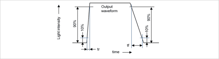
Rise time, tr Fall time, tf |
Rise time, tr, is time required for light intensity to rise from 10 to 90% of maximum output power when drive current is switched on. Fall time, tf, is time required for light intensity to fall from 90 to 10% of maximum output power when current is switched off. (Figure 5) |
| Monitor current, Is | Current of photodiode operated at the specified optical output power, PO . It applies only to a device with a built-in photodiode. |
| Dark current, IDARK | Leakage current of photodiode at the specified reverse voltage without any light input. |
| Capacitance ,Ct | Junction capacitance at the specified reverse bias voltage. |