Technical Support Information - IRED
*IRED series have been discontinued and orders are no longer accepted as of September 30th 2023.
Ushio provide "caution for handling" of iRED to help our customer better understand our products.
Handling Instructions
Suitable handling precautions during device measurement and system design must be taken as described below for high performance of a device with high reliability.
1. The Absolute Maximum Ratings
Be careful never to exceed, even momentarily, the absolute maximum ratings specified in the data sheets herein.
Pay particular attention to the following points.
- It is possible for diodes to be damaged by spike current, generated when switching the power ON or OFF or when adjusting its output voltage. Before activating diodes, check the transient state of the power supply to assure that it does not exceed the maximum voltage rating.
- Operate the diodes below the maximum optical output power rating in order to prevent mirror facet damage and resultant loss in reliability.
- Maximum Ratings are defined at 25 deg C case temperature.
- DO NOT apply higher reverse voltage than Maximum Rating.
2. Surge Energy
Electrostatic discharge and electric spike input which may damage the diodes should be prevented. The main causes of undesirable surge energy are static electricity on the human body, shipping containers made of unsuitable materials, abnormal pulses generated from test equipment, and voltage leakage from soldering irons.
Precautions below should be taken when using diodes.
-
The human body should be grounded through a high resistance of 500 kΩ to 1 MΩ while handling diodes in order to prevent diode destruction due to static electricity contained in the body and clothes.
-
Soldering irons should be grounded to prevent voltage leakage from transferring to the diodes.
-
Suitable materials should be chosen for shipping containers and jigs so that they will not become charged with static electricity by rubbing during transportation. Use of electro-conductive materials or aluminum foil is effective
3. Storage
- Store diodes in temperature of between 5 and 30°C and relative humidity of below 40%. Lower values of both are preferable. Avoid sharp drops in temperature in order to prevent condensation. It is recommended to store diodes in an atmosphere of dry nitrogen with a dew point of –40°C.
- Assure that the storage atmosphere is void of dust and gases harmful to diodes.
- Use a storage case which can not easily be charged with static electricity.
4. Safety Considerations
Even though barely visible to the human eye, laser beams can be harmful to the eye. Do not look at the beam through lenses when the diode is activated. When aligning the optical axis of a laser beam and an external optical system, use an ITV camera (e.g. a silicon-vidicon type) which can detect infrared rays to observe the laser beam.
5. LD-package Handling
G-, MG-, FG-, DG-, TG-, and AT-types
- Take care not to touch the window glass directly. Contamination and scratches on the window surface will result in decreased optical power output and distorted far field patterns. Contamination can usually be wiped off using a cotton swab with ethanol.
- Do not squeeze the cap tightly, as it will cause the window glass to crack and package hermeticity to deteriorate.
- Do not bend the bottom of the lead wire, as it will cause the glass area to crack and the hermeticity to deteriorate.
- Do not cut or process packages.
- Mounting a diode on a thermal radiator
Laser diodes must be mounted on thermal radiators. For higher reliability, it is necessary to minimize mechanical stress to the packages and achieve sufficient heat sinking. Attention should be paid to the following items when mounting diodes on thermal radiators.
-
a. Use a copper or aluminum plate for the thermal radiator. The plate should be larger than 30 × 40 × 2 mm3.
-
To provide good thermal conductivity, polish the thermal radiator surface so it will lie flat with the diode heat sink. Finish the radiator surface to keep bumps, twists, or bends below 0.05 mm.
-
Do not solder packages to thermal radiators, as this may result in excessive temperature to the assemblies inside the packages or loss of package hermeticity.
-
When mounting the diodes, do not touch or hit them against the caps, to prevent the window glass from becoming contaminated or cracked.
-
Do not use silicone grease, as it may contaminate the window glass.
(4) Soldering
-
Soldering point must be away by 1.0mm or more from the bottom of lead wires.
-
Do not allow the scattered flux to adhere to a glass window or a lens.
- Soldering should be done in 10 seconds and at below 260oC.
6. Advice for Beginners
(1) Avoiding surge energy
Laser diodes are easily destroyed by static electricity. To prevent electrostatic discharge, pay attention to the following precautions as well as table 1 when handling diodes and designing application circuits.
-
Set the electric potential of the work bench to the same as that of the power supply ground line.
-
Ground the operator's body by wearing a wrist band as shown in figure 1, and connect it to the same potential as the power supply ground line.
-
Do not operate equipment which may generate high frequency surge energy near diodes. The lead wires of drive circuits pick up surge electricity which may destroy diodes in the induced electric field.

(2) Operating laser diodes
-
Mount a diode on a thermal radiator. The radiator size depends on operating time and output power. When there is no condition set, use a relatively large radiator (50 × 50 × 2 mm3) of copper or aluminum.
-
The drive circuits preferred are ones with APC (automatic power control) function. However, a simple constant current source is recommended when merely testing performance, because adjustment miscalculation can result when circuits are too complex, leading to destruction of the diodes.
-
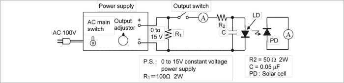
Before connecting a laser diode to the power supply in the ON-state as shown in figure 2, set the output level to the minimum. Also, before disconnecting a laser diode from the power supply, set the output voltage to the minimum. After disconnecting, turn off the main switch.
(3) LD drive circuit
The optical output power from an LD is affected easily by the fluctuations in ambient temperature. An APC (automatic power control) function is generally recommended for a drive circuit to achieve stable operation.
A function which monitors the beam and feeds it back to the drive current is useful to achieve constant optical output power against temperature change.
Table 1 Ways to Prevent Surge Destruction of LDs (Examples)
| Item | Check Points | Specification Examples |
|---|---|---|
| Human body | Ground operator's body. | Place a non-metallic, carbon band with a resistance of 500K Ω to 1M Ω on his wrist. |
| Commonly ground the measuring and inspecting equipment and the work bench. | Should be carried out in shielded rooms as well. | |
| Control the ground level. | Under 10 Ω | |
| Power supply | Distribute power from main power supply through noise filter to each measuring and testing unit. | |
| Insert noise filter in each power supply unit. | Organize with capacitors and resistors. | |
| Keep the main power supply in the on-state, and switch the power on and off using an external switch. | ||
| Set up sequence control for turning the power supply off during electric outages. | ||
| Eliminate relay chattering. | ||
| To prevent chattering, avoid turning the APC circuit or relay switch on and off as much as possible. | ||
| Working conditions | Temporarily stop work when the power supply for lights or other equipment connected to the same power line is turned on or off. | |
| Conduct diode packing and measuring while performing ion blowing or in a weak minus ion atmosphere. | ||
| Select the right soldering iron. | Battery operated soldering iron. | |
| Jigs and other considerations | Make carrier jigs and packing cases conductive. | Particularly the cases. |
| Place conductive mats on the working floor. | 1x10⁴~1x10¹⁰ | |
| Control room temperature and humidity. | Humidity should be 50 ± 10%. | |
| Make short circuits between diode leads. | ||
| Do not use sticky volume knobs. | Periodically replace with new ones. | |
| Eliminate ripples from power supply. | Battery operated power supply. |