光技術情報誌「ライトエッジ」No.29(2007年8月発行)
2006.11 MHS2006&Micro-Nano COE
Surface modification of DMFC using ultra-low energy electron
beam irradiation system with silicon base membrane
Masanori Yamaguchi1*, Yohei Yamada2, Jun Murase2, Yoshiki Goto2, Yoshiaki Nakano3, Shuji hayase4,
Mitsuhiro Shikida1, Kazuo Sato1
1Department of Micro-Nano Systems Engineering, Nagoya University, Nagoya, Japan
2Unit BU, Lamp Company, Ushio Inc., Himeji, Japan
3Corporate Research & Development Center, Toshiba Co., Kawasaki, Japan
4Graduate School of Life Science & Systems Engineering, Kyushu Institute of Technology, Kitakyushu, Japan
1194, Sazuchi, Bessho-cho, Himeji, Hyogo 671-0224
Japan
Abstract
We report the ultra-low energy electron beam(EB) irradiation system as a key tool in order to develop new electrolyte membranes for direct methanol fuel cells(DMFC) applying a barrier strategy. The system called Min-EB consists of EB tube, EB housing and high voltage power supply. Electron beam created from hot tungsten filament by thermionic emission mechanism in the high vacuum tube. EB is passed through the silicon base membrane and emitted into EB irradiation region such as reactor chamber or atmospheric space. Low energy electron beam penetrates only the top surface of electrolyte membranes and improves the characteristics of the membranes.
1. INTRODUCTION
Low energy electron (a few keV) penetrates and interacts with only the top surface without damaging the chemical and physical characteristics of substrate materials. This top surface modification requests the window with small energy loss during the passage of EB window. Min-EB® adopts silicon-base material as EB window because single crystal silicon has toughness, low atomic number, and low density, resulting in low energy loss through window.[1], [2]
In response to worldwide concern regarding toxic emissions and a corresponding rise in demand for renewable power sources, the area of fuel cell technology is one of rapid growth. Over the last decade the DMFC has been identified as a prime candidate for the development of power sources for small portable electronic devices. As fuel cells are attractive as renewable power sources and alternatives to reduce current emission level in ranging from transportation to small portable electronic devices, the polymer electrolyte membrane is recognized as the limiting factor regarding exploitation of this technology. With specific reference to the direct methanol fuel cell (DMFC), where two electrodes separated by a polymer membrane form the core components, performance is largely dependent on the selective permeability characteristics of the membrane.[3], [4]
During operation methanol enters the system at the anode, where it is oxidized generating carbon dioxide [CH3OH(aq) + H2O(l) → CO2(g) + 6H+(aq) + 6e-], while the corresponding reduction process takes place at the cathode, [6H+(aq)+3/2O2(g) +6e- → 3H2O(l)]. A major problem, however, is fuel crossing over from anode to the cathode without producing electricity. If methanol crossover through the polymer-electrolyte membrane is experienced then methanol oxidation can also occur at the cathode, dramatically reducing overall performance. Hence improvements in the selective permeability characteristic of the membrane, facilitating the passage of water but restricting methanol, can produce significant gain in terms of device performance.
One strategy to prepare materials with a high conductivity but low permeability to methanol is the modification of commercially available Nafion® film, creating a thin barrier layer at the surface, Figure 1. Whether modification is by chemical or physical means and is applied to one of both sides of the membrane the bulk of the material remains in tact, presenting the best chance of preserving the inherent conductivity of the parent material. Hence, this approach has been adopted, by us[5]-[9] and others[10], [11], in application to fuel cell technology
2. EXPERIMENTAL
Electron beam irradiation experiments were carried out using ultra-low energy EB irradiation units, both single tube module(STM)-Chamber and Scan-type Min-EB labo from Ushio Inc. Japan. Figure 1 shows miniature electron beam tubes with three and one um thick silicon base windows. The EB tubes are sealed by the glass envelope and the internal pressure of the tube is kept less than 10-6 Torr. The electron beam gun generates electrons from hot tungsten filament by thermionic emission mechanism. The EB accelerated by high voltage power supply is passed through the silicon base membrane and emitted into EB irradiation region such as reactor chamber or atmospheric space.
The silicon base windows are made by process flow of micro-machine lithography showed in fig. 2. Silicon nitride layer is deposited by LP-CVD as a protective layer in order to avoid silicon layer degradation. Plural ribs support eight 2x8mm membranes.
Typical irradiation conditions include an Vacc of 35kV in 760 Torr nitrogen using Scan-type Min-EB labo.[6], [7] Table 1 shows irradiation conditions and relative permeability and conductivity data for 100 um thick Nafion ® films exposured to between 50 and 400uC/cm2 doses on one side using both STM and Scan-type equipment (SCAN).
Irradiation conditions using STM include Vacc of 25- 39kV in 25Torr in order to investigate the effect of the electron penetration depth.
STM-chamber-type equipment includes vacuum chamber and irradiation head that features built-in high voltage power supply as shown in Fig. 3. After the Nafion films have been set in the vacuum chamber, the chamber is purged with nitrogen gas and air in order to at oxygen concentration of 6500ppm. The dose is controlled by the irradiation time.
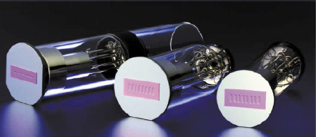
Fig 1 Miniature electron beam tubes with a few micron silicon base membranes.
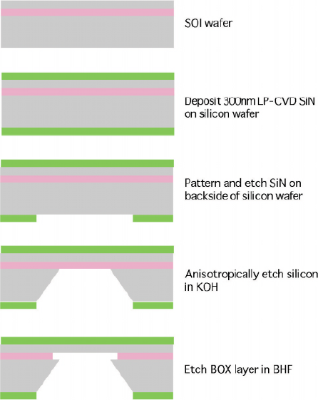
Fig 2 Fabrication process flow for thin membranes as electron beam window.
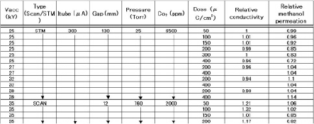
Table 1 Irradiation conditions and relative methanol permeation / conductivity .
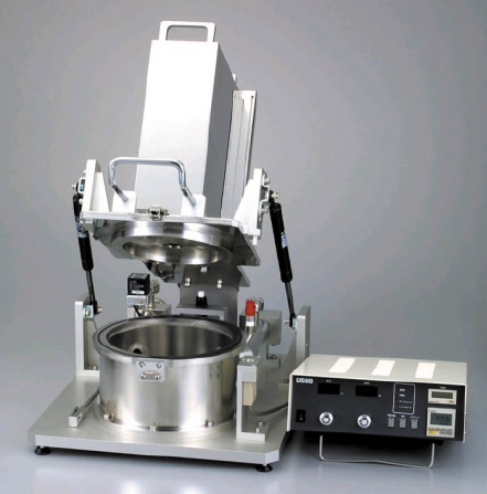
Fig 3 STM-type EB equipment that includes EB tube, EB housing, high voltage power supply, and vacuum chamber.
3. ELECTRON PENETRATION
The electron penetration depth is calculated by MonteCarlo code in order to obtain submicron to a few microns level irradiation depth for selective permeability and electrical conductivity characteristics. Hence, electron should penetrate only the top surface in order not to affect the substrate properties because the polymer electrolyte membrane needs to have original electrical conductivity. Figures 4 and 5 show the Monte-Carlo calculation regarding the electron penetration depth distribution as a parameter of accelerating Voltage in the pressure of 25 Torr Nitrogen and the irradiation gap of 130 mm when the EB windows are three micron and one micron thick respectively. Electron beam irradiation experiments were carried out using ultra-low energy EB irradiation units, single tube module(STM)- Chamber.
Figure 6 shows the electron penetration depth as a parameter of accelerating Voltage in the pressure of 25 Torr Nitrogen and the irradiation gap of 130 mm when the EB windows are three micron and one micron thick. The motivation to develop thinner EB window is to modify only the top surface of target materials and shorten the process time by the reason that thinner window allows more electron penetration and smaller electron energy loss. About 1um thick silicon-base window is newly developed for controlling shallower electron penetration depth and gaining higher EB dose. The electron penetration depth is controlled by the accelerating voltage, gas species, pressure, and irradiation gap.
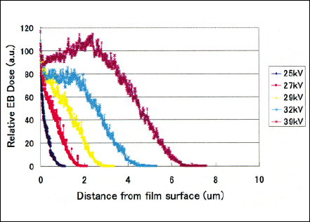
Fig 4 Electron penetration depth distribution of three micron electron beam window tube calculated by Monte-Carlo simulation.
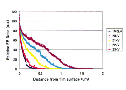
Fig 5 Electron penetration depth distribution of one micron electron beam window tube calculated by Monte-Carlo simulation.
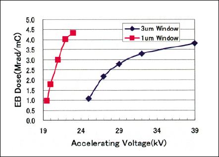
Fig 6 Electron penetration depth of one and three micron electron beam window tubes calculated by Monte-Carlo simulation.
4. RESULTS AND DISCUSSION
Figure 7 shows relative methanol penetration as a parameter of accelerating voltage of STM. The Nafion film exposed at accelerating voltage of 25kV have effects on limiting the methanol permeation although the conductivity is kept at original value as shown in Fig. 8. EB irradiation more than Vacc of 27kV makes the methanol permeation worsen.
To compare two types of EB irradiation equipment, Irradiation conditions to obtain approximately 1µm penetration depth using both SCAN and STM are chosen. The methanol permeation and conductivity of Nafion membranes as parameters of dose in two types of equipment are shown in Figs. 9 and 10 respectively. The methanol permeation of Nafion membranes exposed in two types of EB equipment decrease with the dose of 150-400µC/cm2 regarding. Regarding the electrical property, the conductivity of Nafion membranes are not worsen regardless of type of EB equipment. The EB irradiation by STM does not make Nafion membranes damaged.
According to ATR-IR spectroscopy, EB irradiation results in generating COOH units at the site of polymer backbone and concurrently losing SO3H units.[5], [8] Additional experiments will be required to make mechanism of this surface modification clear.
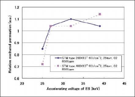
Fig 7 Relative methanol permation against accelerating voltage.
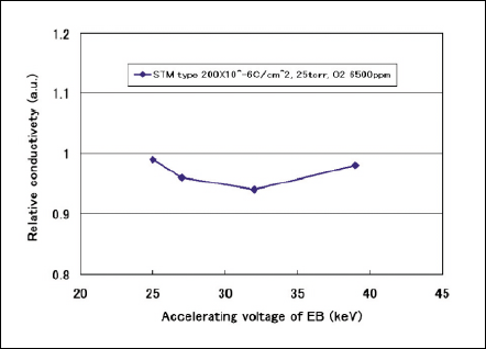
Fig 8 Relative conductivity against accelerating voltage.
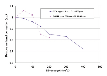
Fig 9 Relative methanol permation against accelerating voltage.
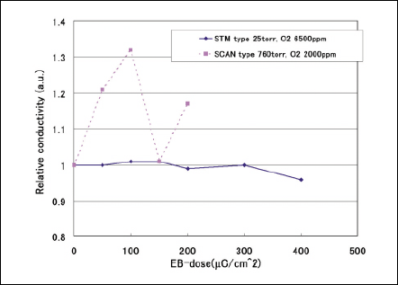
Fig 10 Relative conductivity against accelerating voltage.
5. CONCLUSION
- 1) Electron energy can be controlled using EB irradiation system with thin silicon base membrane in the regime of penetration depth of sub-micron to tens of micron, creating the top surface modification of polymer membranes.
- 2) Methanol permeation characteristics of Nafion membranes exposed in reduced pressure is limited less than original one.
- 3) Penetration depth of more than 2.2µm increases the methanol permeation, resulting in deteriorating the DMFC performance.

