IEEE TRANSACTIONS ON PLASMA SCIENCE, VOL.34, No.4, AUGUST 2006
Self-Consistent Model of HID Lamp
for Design Applications
Khokan C. Paul, Member,IEEE , Tetsu Takemura, Tatsumi Hiramoto, Ahmed Erraki,
Francis Dawson, Member,IEEE , Georges Zissis, Member,IEEE , Jean Jacques Gonzalez,
Alain Gleizes, Mikhail S. Benilov, Member,IEEE , and John D. Lavers, Fellow,IEEE
Abstract
This paper describes a robust and self-consistent high-intensity-discharge (HID)-lamp model implemented on a vendorsupplied computational platform. The model includes a one-dimensional representation of the sheath in the near-cathode region, which allows one to join solutions in the plasma and in the cathode body and thus to self-consistently determine the cathode fall and temperature and current density distribution along cathode's surface. The model has the capability to predict direct-current-operated-lamp properties from the first physical principles without relying on the experimental information (except the confirmation purpose of the predicted results). The P-1 method is used to model radiation transfer, where the mean absorption coefficient for spectral bands is being used to calculate the mean incident radiation for each band. In the scheme developed, the lamp body is divided into a number of domains that are coupled through boundary conditions (for example, boundary conditions for energy and current continuity equations in the plasma depend on the solutions of the cathode and anode models). The complete global solution is obtained iteratively. Properties of interest of the cathode body, the adjacent sheath, the gas-filled region, and the anode body are computed for a typical HID lamp. Results are presented for a discharge medium consisting of an argon-mercury mixture at an operating pressure of 0.11 MPa. The lamp current is 10 A. The predicted maximum temperature and plasma velocity are 10700 K and 8 m/s, respectively, for this particular lamp. Adequate accuracy (experimental validation) occurs under the following operating conditions: a dc current between a few amperes and a few tens of amperes flows in a discharge medium with a pressure from one to a few tens of atmospheres.
Index Terms-Computational fluid dynamics (CFD), computer-aided engineering (CAE), high-intensity-discharge (HID) lamp, mean absorption coefficient, mean incident radiation, P-1 radiation method, spectral band.
I. INTRODUCTION
IN RECENT years, lamp industries have been moving toward computer-aided engineering (CAE), where mathematical modeling and simulation are taking on a greater priority. CAE allows manufacturers to lower their development cost and shorten the development cycle. In many cases, a direct experimental investigation is impossible, and numerical modeling is the only tool that can be used to understand lamp physics, which is inevitably required for producing high quality, reliable, and efficient high-intensity-discharge (HID) lamps.
A number of articles on numerical modeling of HID lamps can be found in the literature [1]-[11]. In [1]- [8], the gas flow was not considered, which produces a critical effect on the temperature and radiation predictions and thus influences the design of the lamp. The models of plasma-cathode interaction developed by Flesch and Neiger [4]-[8] are similar to the one proposed by Fischer [1] and rely on some physically unjustifiable simplifications, such as the use of the principle of detailed balancing in order to relate rate constants of processes that are not direct and inverse, and neglect the presence of the space-charge sheath. Note that the latter simplification prevents these models from predicting high near-cathode voltages observed in the experiment at low currents (e.g., [16]). The three-dimensional (3-D) model of Galvez [10] has included most physical aspects of plasma and electrodes, although not of the glass bulb.
Our previous paper [12] reported on plasma behavior on the basis of assumed boundary conditions at the fluid-solid interfaces. In this paper, we describe a self-consistent model for the plasma and electrodes, where boundary conditions at the plasma-electrode interfaces are based on the coupled solutions for adjacent domains. The model takes into account most physical phenomena associated with an HID lamp (ignoring turbulence and fluid-compressibility effects as these are insignificant) and can produce all the information required for design purposes, such as spatial distributions of temperature, velocity, specie densities, electromagnetic effects, radiation, etc. A commercial computational- fluid-dynamic (CFD) software package Fluent 1 is used as the computational platform, where customized application modules are used for solving the physical models. For implementation convenience in Fluent (version 6.1), the lamp is divided into a number of sections that are modeled separately. The required boundary information at the fluid-solid interfaces is generated automatically in the Fluent computational environment. The sections considered in the model are the cathode sheath and body, the plasma or gasfilled region, the anode body, the glass bulb, and lamp enclosure or exterior domain. Common and conserved boundary solutions are attained through an iterative process whereby information is exchanged between the adjacent sections. This paper focuses on the sections that deal with the electrodes, including cathode sheath, and plasma.
Radiative transfer, which is one of the most important issues in HID lamps or radiation sources, is introduced into the calculation using the P-1 radiation method. This method uses a mean absorption coefficient for each spectral band. Usually, special design attention is given to have the optimum radiation output from a desired spectral band based on the lamp or radiation source’s application. P-1 radiation method has been chosen because it is simple to implement and gives adequate results under many operating conditions of interest to the designer, even though it is found to overestimate the radiation flux especially for systems dominated by optically thin radiation [13]. A disadvantage in calculating the mean absorption coefficient is that the user must specify a plasma radius that is an empirically determined value.
The significant amount of computational time, which is required to implement an exact calculation procedure for radiation, is not practical especially from the perspective of industry. The implementation of the partialcharacteristic method, which is a method claimed to treat radiation accurately irrespective of opacity, can reduce the calculating time by four orders of magnitude over an exact calculation [14], but this is still very time consuming. Moreover, Dixon et al.[15] has reported its poor performance compared with the P-1 method for arcs burning in axially dominated flow inside a nozzle, meaning the method may fail to provide any advantage for some discharges. Another attractive model for radiation is the discrete-ordinate (DO) method. Unfortunately, the accuracy of this model also depends on the degree of directional discretization. An increase in the directional discretization increases the accuracy but also increases the computational time. Moreover, the available version (Fluent 6.1) of the vendor-supplied CFD package does not allow the use of a temperaturedependent mean absorption coefficient for each frequency band. In summary, the tradeoff of complexity,computing time, cost, and accuracy still make the P-1 radiation method attractive for our type of engineering applications.
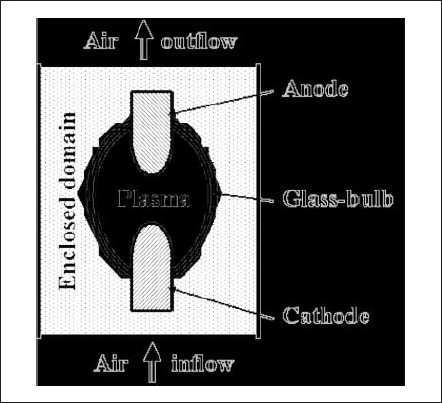
Fig. 1. General schematics of an HID lamp and its enclosed domain.
The realizable attractive features of the developed model are the following: a one-dimensional (1-D) cathode-sheath model that calculates the thin space-charge layer in nonequilibrium as a separate entity and is interfaced in a simple fashion with the cathode body and the equilibrium plasma, the ability to produce substantial information on lamp properties for new geometries and/or operating conditions using only physical properties, free from the dependence on experimental data other than for validation purposes, and the ability to give a partial prediction instantaneously since the model considers a section as a separate entity.
The operating pressure of HID lamps is usually more than 1 MPa, and at this pressure range, the plasma column can be assumed to be in local thermodynamic equilibrium (LTE) but not in the vicinity of electrode tips or the glass wall enclosure. These regions must be modeled on the assumption of non-LTE physics. Fortunately, only the cathode region is important to be modeled more accurately. A geometrically decoupled model of the nonequilibrium sheath has the benefits of isolating non-LTE and LTE regions and thus avoiding complexity.
For purposes of illustrating the developed model, calculations are done for an arbitrary geometry and operating conditions on an HID lamp that has not been produced commercially. The lamp has a rotational symmetry and is assumed to be vertically oriented with the anode at the top. Operating conditions are chosen as follows: a direct current (dc) of 10 A, an operating pressure of 0.11 MPa, and a discharge medium consisting of a mercury-and-argon mixture with a mass concentration of 91% and 9%, respectively. The considered operating pressure is far lower than those of practical HID lamps.Like the other specs, operating pressure is chosen to be far off from those of commercial lamps.
II. COMPONENTS OF THE MODEL DESCRIPTION
The lamp is divided into a number of sections and modeled separately. Information is exchanged between adjacent sections in order to satisfy the interfacial boundary conditions. Fig. 1 illustrates the overall schematics of the lamp. Note that the model and results for the lamp-enclosed domain and glass-bulb region are not presented in this paper.
A. Cathode and the Near-Cathode Plasma Layer
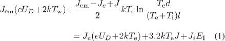
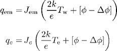
Over the last ten years, there have been numerous investigations on the plasma-cathode interaction in high-pressure arc discharges, both experimental (e.g., [16], [17]) and theoretical (e.g., [18]-[26]). Our work is based on the model of Benilov and Marotta [18], which, with some modifications, has been used in subsequent works and has produced results that are in good agreement with the results of both thermal and electric measurements [16], [22]. In this paper, the model [18] is changed as follows: The ion motion across the space-charge sheath is treated as collisiondominated, and the sheath is described by means of the solution [21]; the work function of thoriated tungsten cathode (which depends on the lattice structure of the cathode surface and the degree of coverage by thorium) is evaluated according to [27]. The model may be summarized as follows. Let us consider a near-cathode plasma layer of a thickness of a few tens of micrometers that consists of a presheath (the ionization layer) and the sheath (the space-charge layer). The electron temperature is assumed to be constant in the near-cathode layer and is governed by the equation of balance of electron energy in the ionization layer
where the density of electron emission current, the density of the current transported by electrons counterdiffusing from the plasma to the cathode surface, and the ion current density, respectively, are
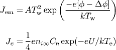
and
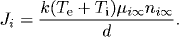
Here, UD and U are the voltage drops in the sheath and in the whole near-cathode layer (sheath+presheath), respectively; Te , Ti , and Tw are the electron, ion, and cathode-surface temperature, respectively; e is the electronic charge; k is the Boltzmann constant; l and d are the lengths defined in [21]; A is Richardson’s constant; φ and Δφ are the work function of the thoriated-tungsten cathode material (2.855 eV for the degree of surface coverage one [27]) and Schottky correction, respectively; Ce is the electron’s mean thermal speed; E1 is the ionization energy of atomic mercury (10.43 eV); and ni∞ and µi∞ are the ion density and mobility, respectively, at the edge of the ionization layer and bulk plasma.
The left-hand side of (1) represents the energy carried into the ionization layer by the electrons emitted by the cathode surface and the energy generated by the work performed by the electric field on the electrons in the ionization layer. The terms on the right-hand side are the energy carried away from the ionization layer to the sheath by the electrons, the energy carried away to the bulk plasma by the electrons, and the electron-energy loss due to collisions with the heavy particles of the layer, respectively.
The model described above is written under the assumption that the ion motion across the space-charge sheath is dominated by collisions. This assumption is marginally valid for a near-atmospheric discharge and is well justified at higher pressures. Although this paper assumes a near-atmospheric pressure of marginal validity for collisional sheath, we choose such sheath refering the practical HID lamps of high pressure.
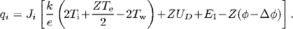
Equation (1) is solved by the Newton-Raphson iterative method for a given cathode fall (U)and cathode-surface temperature (Tw). After a solution has been obtained, the net current density J (=Tem + Tt -Te )and the net energy flux from the plasma to the cathode surface q (=qe +qi -qem ) are calculated. Note that the heatflux components have the following expressions:
and
Here, Z is the ion-charge number. Mercury’s partial pressure is used in this calculation due to its very low ionization energy.
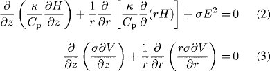
By performing this procedure for all U and Tw of interest, one can generate the lookup tables of current density and heat flux. As an example, these tables are shown in Fig. 2 for mercury pressure of 0.1 MPa. As can be seen in Fig. 2(a), the current density continues to increase even above the melting temperature of 3680 K because the emission current rises substantially. However, the temperatures higher than 3680 K (of Fig. 2) are less important for commercial HID lamps because, with rising temperature, the cathode surface cools down by the significant energy loss due to electron emission that eventually prevents overheating of the surface.
Inside the cathode body, the energy balance and current continuity equations are solved
where Κ and σ are the thermal and electrical conductivities of the cathode material, respectively, H and Cp are the enthalpy and the specific heat at constant pressure, respectively, V and E are the electrostatic potential and electric-field intensity, respectively, and z and r are the axial and radial coordinates, respectively.
Fig. 2. Calculated current density and heat flux as function of cathode-surface temperature for parametric potential drop at the near-cathode region (sheath and presheath).
B. Anode
The same energy balance and current continuity (2) and (3) are solved also inside the anode body. The presence of the near-anode plasma layer is neglected (i.e., it is assumed that the plasma is quasi-neutral and in thermal and ionization equilibrium right up the anode surface). Note that the anode fall, which is disregarded in the framework of this approach, is usually very small and does not play a significant role in dc-operated HID lamps of operating current between a few amperes and a few tens of amperes.
Material properties (electrical and thermal conductivity, enthalpy) of pure tungsten are used in solving both the cathode and anode domains. These values are taken from [28].
C. Bulk Plasma
In predicting the important discharge properties (like temperature, velocity, electromagnetic interactions, etc.) of an HID lamp, it is necessary to solve the complete set of magnetohydrodynamic (MHD) equations. These are basically the transport equations for mass, momentum, and energy conservation including the electromagnetic effects (Lorentz force in the momentum equation and Joule loss in the energy-balance equation). The P-1 radiation method is used to calculate the radiative-loss term in the energy-balance equation. Laplace’s equation (3) is used to calculate the electric field. The curl of Ampere’s law, in a differential form, is used to calculate the magnetic field. The specie-conservation equation is used to predict specie diffusion. The expressions used for all equations are given below.
Mass continuity
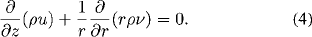
Momentum conservation
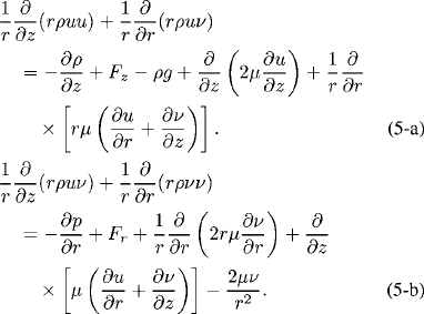
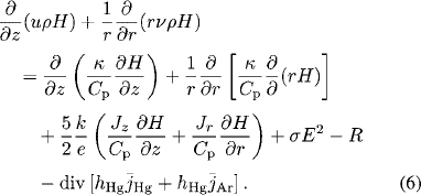
Energy conservation
Curl of Ampere’s law

Specie-conservation equation for argon
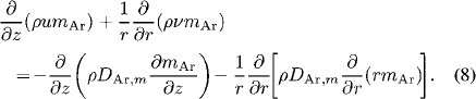
Here, ρ and µ are the mass density and viscosity, respectively; hHg and hAr are the enthalpies and  and
and  are the diffusion fluxes of mercury and argon, respectively; mAr and DAr m are the local mass concentration and diffusion coefficient of argon, respectively; u and v are the axial and radial velocities, respectively; Bθ is the azimuthal component of the magnetic- field intensity; Fz (=curl of current density and magnetic- fieldintensity vectors in the z -direction) and Fr (=curl of current density and magnetic-field-intensity vectors in the r - direction) are the axial and radial Lorentz forces, respectively; Jz and Jr are the axial and radial current densities, respectively; and g and µ0 are the gravitational acceleration and permeability of free space, respectively. R on the right-hand side of (6) is the volumetric radiative loss and is calculated from the mean absorption coefficient and the mean incident radiation for spectral band i
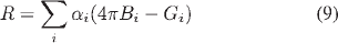
where αi , Bi , and Gi are the mean absorption coefficient, weighted Planck’s function, and mean incident radiation, respectively.
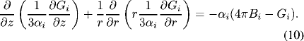
The mean incident radiation Gi is calculated by the P-1 radiation method [12]. In P-1 method, a Helmholtz-type equation of the following form is solved for band i :
The electromagnetic spectrum between the wavelength 100 and 20000 nm is divided into five bands: 100-119, 119-680, 680-1200, 1200-4500, and 4500-20000 nm. Therefore, five equations having the form similar to (10) are solved to calculate the radiative energy using the mean absorption coefficients. Special care is exercised in partitioning the spectrum such that the absorption coefficient due to the continuum radiation is approximately the same within a band; this is the criterion proposed in developing the mean-absorptioncoefficient model [29]. An increase in the number of bands leads to an increase in the computing time since one equation is required to solve for one band. The band divisions are seen optimal for this particular gas combination and operating pressure: Optimal in the sense that the plasma temperature and other properties are found not to change significantly with the increase of band numbers. The material and optical properties of the discharge medium are our calculated values; calculation procedures and results have been reported in [12].
In modeling the bulk plasma, LTE assumption is adopted. Plasmas are usually in LTE at higher pressure. However, near- atmospheric pressure plasmas can also be considered in LTE fairly accurately especially for the case of a steady-state operation [30].
For modeling the glass bulb, the radiation-included energy-balance equation for a semitransparent glass medium is solved. This paper does not include a description of this model.
III. BOUNDARY CONDITIONS
The physical models for the different sections are subject to boundary conditions. The boundary conditions for the cathode, plasma, and anode sections are explained below.
A. Cathode Boundary Conditions
Fig. 3 shows the simple schematic for the cathode. Boundaries C1 , C2 , and C3 are the contacts with the hotter plasma, colder plasma or gas, and outside air, respectively. Boundary Co is at the far end and is usually close to room temperature.
Initially, an arbitrarily chosen constant potential is specified at C1 for solving the current continuity equation. Corresponding to this potential, the solver chooses heat fluxes from the lookup table, which is generated by solving the sheath model, for the energy-balance equation. Details are explained in Section IV.
At the C2 boundary, a temperature profile is specified first and then switched to a heat-flux profile.
At the C3 boundary, a heat-flux boundary condition is specified using the heat-transfer coefficient that comes from an enclosed-domain solution. Current densities are set to zero for both C2 and C3 .
Room temperature and a current density associated with the lamp current of 10 A are given at the boundary Co .
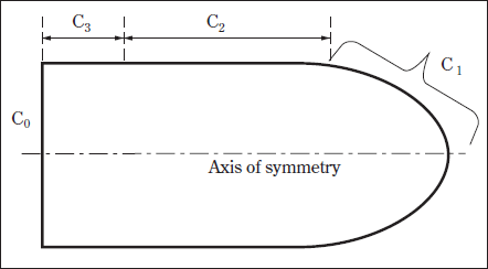
Fig. 3. Schematics of the cathode body used in the cathode model solution.
B. Anode Boundary Conditions
As shown in Fig. 4, Ao is the far-end boundary of the anode. At this boundary, the room temperature and the current density associated with a lamp current of 10 A are defined. For boundaries A2 and A3 , similar boundary conditions to those of C2 and C3 , respectively, are specified. At A1 , a heat flux and a constant reference potential are specified for the energy and current continuity equations. This heat flux is the summation of the flux due to current flow ( Jφ), flux due to electronic enthalpy, flux due to net radiation at the surface, and flux due to convection. All of these components are available after a plasma solution. For the tungsten anode, a work function (φ)of 4.5 eV is used. Note that the anode may adsorb thorium, which is likely be present in plasma due to cathode’s evaporation, thus the work function may vary from the ideal value of 4.5 eV.
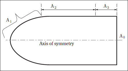
Fig. 4. Schematics of the anode body used in the anode model solution.
C. Plasma Boundary Conditions
The schematics of the discharge or gas-filled region of the lamp are shown in Fig. 5. On the axis of symmetry (AD), symmetry conditions are imposed. For the energy conservation and current continuity equations, the boundary conditions at the cathode-gas (CD) and anode-gas (AB) interfaces are obtained from the cathode- anode solutions. Current density is set to zero at the glass boundary (BC). Velocities are specified as zero at all boundaries. For the specie-conservation equation, diffusion flux is set to zero at all boundaries. For the P-1 radiation method, Marshak’s boundary condition [13], [31] is used to specify the boundary flux for mean incident radiation
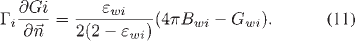
Here, Γi (=1 /3 αi )and εwi are the diffusion coefficient and mean hemispherical emissivity of the boundary wall, respectively, for spectral band i .  is the outward normal vector to the boundary. Temperature-dependent electrode and glass emissivities are taken from [28], [32], [33], and [34]-[36], respectively. These are arranged to produce the mean emissivity of bands, as shown in Fig. 6.
For solving the azimuthal magnetic field, the following boundary conditions are applied:
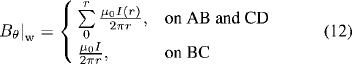
where Bθ|w is the wall magnetic field.
The temperature at the glass-gas interface (BC) is specified as a constant value of 800 K. Solution of the glass-bulb model can be used to determine the actual temperature of the wall.
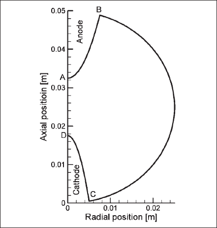
Fig. 5. Schematics of the gas-filled region of computed lamp.
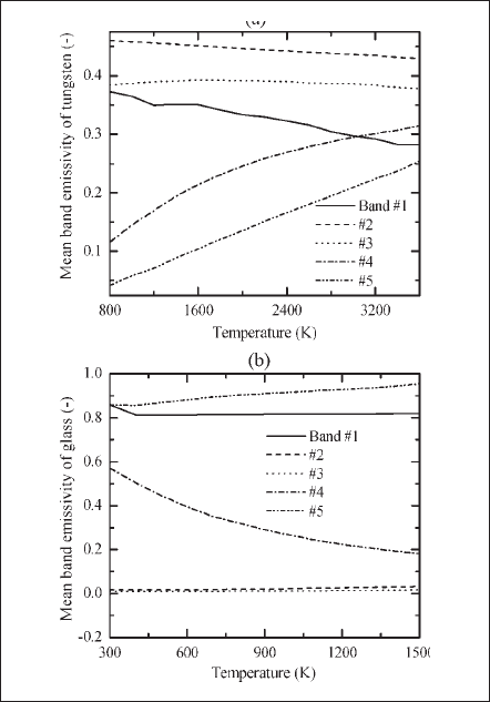
Fig. 6. Temperature-dependent mean hemispherical emissivity of bands. (a) Tungsten. (b) Fused quartz glass.
IV. METHODS OF SOLUTION
Using the lookup tables obtained from the near-cathode-region model, the cathode-body model is solved for the current density and temperature distributions at the surfaces. The specified heat flux at the cathode tip (C1 of Fig. 3) is shown in Fig. 2(b) and is related to the surface temperature and potential. At this stage, the heat flux does not include the radiation effect since the net radiation effect is available only after the plasma solution. When the solution for the specified potential is achieved, the current density and the total current at the cathode surface are postprocessed by using the profile of Fig. 2(a). Using the postprocessed current density, the total current at the cathode surface is calculated. If the calculated total current is not equal to the desired lamp current, the value of the specified potential is changed for a new solution and postprocessing. Thus, the current density distribution for the desired lamp current and the temperature distribution are obtained iteratively by changing the value of the potential. The potential at the cathode tip, for which the solution at rated lamp current is obtained, is referred to as the cathode fall.
With known values for the current density and temperature distributions at the cathode surface, the next step is to obtain a solution for the plasma region. When the converged solution is reached for the plasma domain, the heat-flux density at all boundaries and the current density at the anode surface are known.
The heat-flux density and current density at the anode surface are used to compute the temperature distribution on the anode body. The converged solution of this model produces the temperature distribution at the anode/plasma interface, which is then used for calculating the plasma solution in the next iteration. In order to update the distributions at the cathode/plasma interfaces, the cathode-body model is solved again using the calculated values of the heat-flux density. At this stage, the total flux at the current-carrying region of the cathode surface is the summation of the net radiative flux (obtained from the plasma solution) and the flux shown in Fig. 2(b). At the cathode/plasma interfaces C2 and C3 of Fig. 3, total heat fluxes (from the plasma solution) are used as the boundary conditions.
Thus, an iterative calculation scheme (cathode-plasma-anode-cathode) is performed until the temperatures at the interfaces are found to remain unchanged, or an overall convergence is achieved. After convergence, a cathode-surface potential of 12.8 V, which is the cathode fall, is found to produce a current density distribution that leads to a corresponding total lamp current of 10 A.
V. RESULTS AND DISCUSSION
In this section, the results for the cathode, anode, and plasma models are presented and discussed. Although a number of iterations have been executed to achieve the converged and common boundary solutions, results for different sections are presented for the final runs. Converged solutions have been achieved for all domains, and conservation rules at boundaries have been satisfied.
A. Cathode and Anode Results
Fig. 7 presents the isotherms in the cathode and anode bodies. The current density distribution of the currentcarrying zone of the cathode surface and temperature distribution at the cathode and anode surfaces are shown in Fig. 8(a)-(c), respectively. For this particular geometry and operating conditions, a cathode fall of 12.8 V has been predicted for a thorium coverage degree of one. These calculated profiles are used as boundary conditions in plasma simulations for the last step of the iterative scheme.
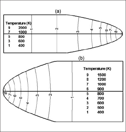
Fig. 7. Isocontours of evaluated temperature. (a) In the cathode body. (b) In the anode body.
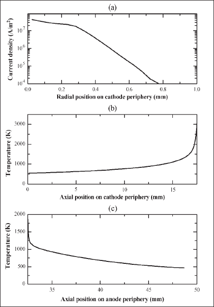
Fig. 8. Surface distributions obtained from electrode modeling. (a) Current density at the cathode-plasma interface. (b) Temperature distribution at the cathode surface. (c) Temperature distribution at the anode surface.
B. Plasma Results
The isocontours of temperature (right) and electrostatic potential (left) are shown in Fig. 9. For an interelectrode gap of 15 mm, the arc drop was found to be about 23 V (surface near the cathode tip is at the maximum potential with respect to the anode but this isocontour is not apparent in the figure). The total potential drop (viz. cathode fall +arc drop ) for this lamp is about 35.8 V. Plasmas near the tips of the electrodes are very hot, and the maximum temperature in these regions is 10 700 K. The axial gradient of temperature and all other plasma properties near the cathode tip are the stiffest, and the temperature gradient is very significant near the anode tip. Temperatures in the intermediate regions between electrodes are lower but occupy a larger volume, meaning that the plasma converges at the electrodes and diverges between the electrodes.
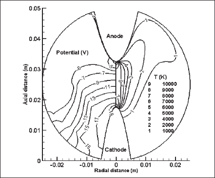
Fig. 9. Isocontours for electrostatic potential (left) and temperature (right) over the gas-filled region.
Fig. 10 presents the isocontours of current density(left) and velocity magnitude (right) of the discharge domain. The constricted current flow at the cathode surface diverges between the electrodes and again constricts at the anode surface. However, the current carrying zone at the anode surface is larger than that at the cathode surface: Current flows through a circular area of radius 0.6 mm at the cathode surface and a radius of 0.8 mm at the anode surface. In a practical HID lamp, the current at the anode surface is usually more diffuse, which is mainly due to the anode’s design and shorter interelectrode gap. The velocity magnitude is a maximum of about 8 m/s near the cathode tip. It is high at the anode tip too. Significantly, high Lorentz forces near the electrode tips, which are due to the constricted electromagnetic fields, are the dominant driving forces for high plasma velocities near the electrode tips. The effect of Lorentz forces in an HID lamp was recently discussed in [37].
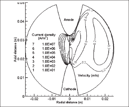
Fig. 10. Isocontours for plasma current density (left) and velocity magnitude (right) over the gas-filled region.
The specie-diffusion effect of the mixture is depicted in Fig. 11, where the contours of argon and mercury concentrations are drawn in the left part and right part, respectively. Argon, which is about five times lighter than mercury, moves upward making its concentration higher around the top of the lamp (around the anode),whereas the heavier mercury concentration is higher at the bottom part (around the cathode). Specie diffusion changes the material and optical properties of the mixture, and thus, it affects the overall radiation output and/or lamp performance.
Contours of the volumetric Joule energy (left) and radiative loss (right) are presented in Fig. 12. Contour profiles of volumetric Joule energy are obviously similar to those seen for the current density in Fig. 10 (left). The maximum energy densities are found near the electrode tips. Volumetric radiation loss is the radiative loss term (R)of the energy balance (6). It is the divergence of the radiative heat flux and is the total contribution of all five bands. This energy is apparently significant within the plasma region where the plasma temperature is in the range of 4000 K or above (refer to the temperature contours of Fig. 9). The vanishing mean absorption coefficient and weighted Planck’s function at a temperature below 4000 K leads to a decrease in the radiative loss at lower temperatures. At the plasma boundary and in the cooler region of the discharge, net absorption instead of net emission takes place, and the volumetric radiative loss becomes an additive term (source) in the energy balance. Only one contour (number 1) of -4 W/m3 is shown as a net absorber within a small region. Here, the negative sign implies that the net radiation has changed direction, or it acts as a source instead of a sink of energy.
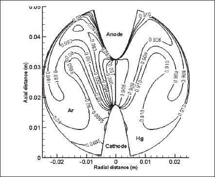
Fig. 11. Isocontours for mass-concentration ratio of argon (left) and mercury(right) over the gas-filled region.
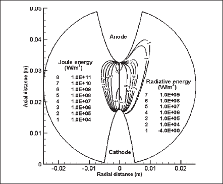
Fig. 12. Isocontours for volumetric Joule energy (left) and radiative energy (right) over the gas-filled region.
As mentioned before, the radiation effect for the electro-magnetic spectrum between 100 and 20 000 nm has been accounted for, and the considered span has been divided into five bands. The mean incident radiation for each and every band is calculated. As a representative illustration, Fig. 13 shows the isocontours of the mean incident radiation for bands 2 (left) and 3 (right). In this particular case, the mean incident radiation of band 2, which includes ultraviolet through the visible region, is larger by an order of magnitude than that of band 3, which accounts for the infrared region. Applying this technique, the radiation output from a desired wavelength or band of wavelengths can be evaluated. Usually, an information on the radiation output from a particular frequency band relative to an application is desired in designing an efficient lamp or radiation source.
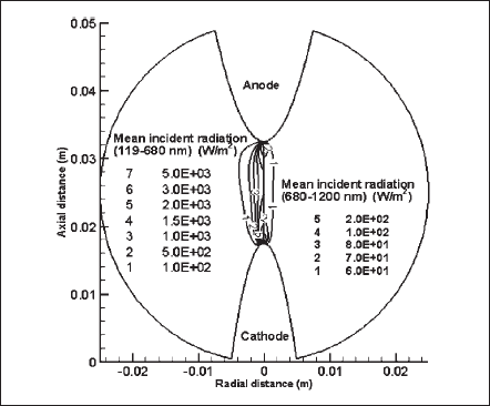
Fig. 13. Isocontours for mean incident radiation of wavelength band 2 (left) and band 3 (right) over the gas-filled region.
The lamp geometry of the article is used only to present the model and its performance. For validation purpose, the model has been applied to predict the properties of a commercially available high-pressure mercury lamp. The lamp’s total voltage drop(arc+cathode fall) has been predicted within 10% of the supply voltage. In such a lamp, the cathode fall has been calculated as about 10 V. To compare the radiation outputs, the spectral radiation between 250 and 1000 nm has been measured experimentally outside the lamp and was transferred to the inner glass surface of the lamp considering the glass thickness and optical properties. A comparison of the radiation output at the inner glass surface over the wavelength region has shown a very good agreement (within 10% accuracy). However, when a band has been specified, where lines are densely populated, the predicted radiation has been found to differ by a maximum of 30%. Moreover, the predicted temperature distributions at the electrode’s surface have shown a maximum difference of 100 K (a deviation of 4%) with those of the experimentally determined temperatures. Note that temperatures very close to the electrode tip (within a length of 3 mm from the tip) were difficult to measure accurately, and hence, the comparison has been done over the electrode’s surfaces along the lengths that are 3 mm away from tip. All of these results suggest that the developed model predicts the steadystate properties of a direct-current operated HID lamp with an accuracy that is acceptable to a lamp designer.
VI. CONCLUSION
A robust self-consistent model that accounts for the glass enclosure, glass seal, cathode-layer effects, the electrodes, and a plasma has been developed for a DCoperated HID lamp. The merits of the model are that it treats the non-LTE thin cathode-layer sheath separately and is easily interfaced with the electrode and plasma region. Trends in solutions for any section of the lamp can be viewed instantaneously without waiting for a converged solution for the whole lamp system. For a desired specification, the proposed modeling approach evaluates most of the steady-state parameters of interest for the whole body of the lamp between the two powersupply ends with sufficient accuracy. The solution of the cathode (with sheath) and anode models has been used to determine the current density and temperature distributions at the cathode surface and temperature distribution at the anode surface, respectively. These distributions have been used as boundary conditions in modeling the plasma or gas-filled region of the lamp. A domain-to-domain iterative scheme has been adopted exchanging the information between the adjacent domains until a conserved and unaltered temperature at the interfaces is achieved. The glass-bulb model (which is not described in this paper) has similar features and is useful for calculating the temperature distribution in the glass and the radiation output from the surface of the glass. The complete model produces most data from first principles and does not need any experimental data other than for validation purposes. For the presented arbitrary geometry and operating conditions, the maximum plasma temperature is found to be 10 700 K, the maximum velocity is 8 m/s, and the total lamp voltage drop is 35.8 V.
The practical application of our model suggests that it can predict lamp properties with adequate accuracy for the following operating conditions: a dc current between a few amperes and a few tens of amperes, which burns a discharge medium with a pressure from one to a few tens of atmospheres.
ACKNOWLEDGMENT
The authors would like to thank M. Sakai and Y. Aiura for performing the experiments and supplying results, which were compared with the theoretical findings.