光技術情報誌「ライトエッジ」No.35(2011年8月発行)
2011.3 SPIE Advanced Lithography 2011
Sn film and ignition control for performance enhancement
of laser-triggered DPP source *
Yusuke Teramoto, Takuma Yokoyama, Hideyuki Urakami and Kazuaki Hotta
Extreme Ultraviolet Lithography System Development Association,
Gotemba R&D Center, Germany Branch
15 Steinbachstrasse, Aachen 52074, Germany
ABSTRACT
A laser-triggered DPP source is being developed and showing considerable progress toward HVM. Performance, in terms of power and lifetime, of DPP sources has been proven by long-term usage in lithography development fields. Since high-performance debris-mitigation tools are used in DPP sources, collector lifetime is not an issue. However, it is worth developing the technology to enhance overall lifetime of the collector module. In order to suppress both neutral and ionic debris, two technologies, which can be simultaneously used in a DPP source, have been developed. First, a discharge ignition by using two lasers was developed. It was able to reduce the amount and energy of fast ions which could sputter a collector by a factor of 5. In addition to fast ion reduction, CE enhancement of 60% was obtained. Second, an active control of liquid tin layer, which acts as a fuel material, electrode protection and cooling medium, could reduce particle debris and lower the load of a debris-mitigation tool. Implementing these technologies is considered to provide enhancement of the lifetime of the collector module and support HVM readiness.
Keywords: EUV, laser-triggered DPP, Sn, HVM
1. INTRODUCTION
EUV lithography is being developed for the next generation semiconductor manufacturing technology. Several alpha tools are being used worldwide1 and demonstrating excellent performances such as small feature size. Recently, beta tools are being put into operations at some device manufacturers and institutes. In order to realize volume production of EUVL, >180 W of EUV power at the entrance of exposure tool is required2. Source power must be increased by a factor of 5~10 from the present level. Therefore, EUV source is being considered as the principal issue of EUVL technology3. In addition to the source power, reliability is obviously important for pre-production and production sources. EUVA has been working on a laser-triggered discharge-produced plasma source. It uses a rotating electrode which turns through a container where liquid Sn is flowing. Here liquid Sn plays several roles; current conduction between an electrode and capacitor, fuel material of λ=13.5 nm radiation, cooling medium for the electrode, and surface protection of the electrode. Because electrode surface is always covered by liquid Sn, there is not a bombardment- like direct current contact between high-density plasma and electrode material. Therefore, lifetime of the electrode is, in principle, unlimited. Furthermore, liquid Sn is actively circulated around the electrode taking heat from it. Liquid Sn has very efficient cooling capability compared to a conventional water-cooled system.
In a DPP source, a mechanical debris-shield, so-called foil trap, is used to protect collector optics from debris. A foil trap is so efficient that almost all debris are trapped and lifetime of the collector is no longer an issue. However, a part of ions pass through the foil trap and sputter the collector surface gradually. In order to enhance the performance of the sourcecollector module (SoCoMo), especially foil trap and collector, it is worth to reduce the load of the foil trap by reducing amount of particle debris and to reduce the sputtering rate by reducing amount of fast ions. In this paper, a newly-developed Sn film control and discharge ignition control will be described.
* Work supported by NEDO.
c/o XTREME technologies GmbH, 15 Steinbachstrasse, Aachen 52074, Germany
URL: http://www.euva.or.jp
2. EUV SOURCE CONFIGURATION
Fig. 1 shows a conceptual diagram of a laser-triggereda DPP source. Two electrode wheels are immersed in liquid Sn and rotating around the axes. When the capacitor which is directly connected to the electrode assembly is charged, trigger lasers are fired to ignite the discharge. Note that only one laser is sufficient to ignite the discharge. The second laser controls the condition of initial plasma before EUV radiation is emitted to reduce fast ions and enhance conversion efficiency. Radiation, particle/neutral debris and ionic debris are emitted from the plasma. All particle/neutral debris and most of ionic debris are trapped by the foil trap. A part of ions passes through the foil trap to cause sputtering of the collector surface. Although fast ions decide the lifetime of the collector, they have a positive effect as well. Fast ions prevent the reflective surface of the collector from deposition of Sn. This scheme has been proven by years of operation of alpha sources. In this scheme, only clean photons are emitted after the collector toward the scanner.
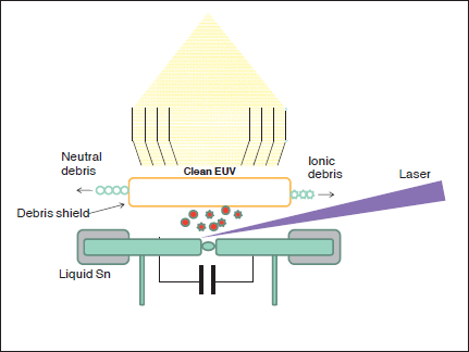
Fig. 1: Conceptual diagram of laser-triggered DPP source.
3. TIN THICKNESS CONTROL
Fig. 2 shows a conceptual diagram of the electrode assembly. An electrode wheel is rotating through the container in which liquid Sn is circulating. In order to control the thickness of the Sn layer on the electrode, a wiping mechanism is equipped in the electrode assembly between Sn container and the point of discharge. The higher discharge frequency is, the faster wheel rotational speed is required. Due to the centrifugal force, liquid Sn tends to splash off the electrode surface. Therefore it is very important to control the thickness of liquid Sn. Moreover, due to the bombardment by large current, top surface of liquid Sn layer explodes to cause particle debris flying toward the foil trap. These particle debris are completely captured by the foil trap. It is needed for reducing the load of the foil trap to reduce the amount of particle debris by reducing Sn layer thickness.
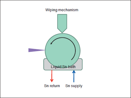
Fig. 2: Conceptual diagram of electrode.
Fig. 3 shows a comparison of Sn film thickness as a function of wheel velocity for two different types of wiping mechanisms. A conventional (passive) wiper shows that Sn layer thickness increases up to 1 (nominal value) at the velocity of 3, then thickness reduces with increasing wheel velocity. Sn layer thickness for the conventional wiper is not so thin that Sn layer collapses at certain speed resulting in the decrease in thickness. In the case of conventional wiper, it is clear that thickness is not maintained over the wheel velocity. On the other hand, a new type of wiping mechanism could control Sn layer thickness over the wide range of wheel speed. Sn layer thickness was reduced by a factor of 5, from 1 to 0.2, and maintained over at least twice higher wheel speed. Sn layer thickness obtained by this new scheme is sufficiently thin to reduce the amount of particle debris but sufficiently thick to protect the electrode surface.
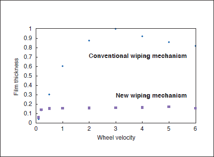
Fig. 3: Sn layer thickness as a function of wheel rotational velocity.
Fig. 4 shows an example of the active control of temperature of liquid Sn. Liquid Sn is circulating through the electrode and taking heat out of the electrode. A Sn circulation system is attached to the electrode, by which liquid Sn is cooled and maintained at the constant temperature. In this example, input power was varied from 1 to 15 kW in 90 minutes. After active temperature control (cooling) was turned on, the temperature of liquid Sn was maintained at almost constant level while input power was varied by an order of magnitude.
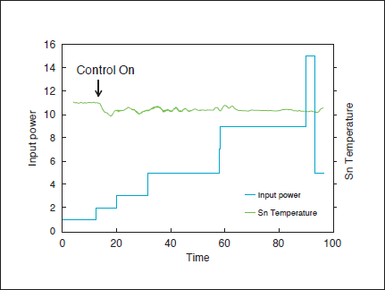
Fig. 4: An example of liquid Sn temperature control.
As a result of the developed Sn film control, amount of particle debris was significantly reduced as shown in Fig. 5. Evaluation of particle debris was done by placing Mo witness plates at 30 cm away from the plasma. After 1 Mpulses of exposures, these samples were observed with an optical microscope to count the number of particles of each size. In the case of the new wiper, significant reduction of debris particles was observed for all particle sizes. Overall (averaged) particle reduction factor of the new wiper compared to the conventional wiper was three. It can be concluded that the new wiper makes Sn layer very thin enabling fast wheel rotational speed and three times less particle debris emission from the source plasma.
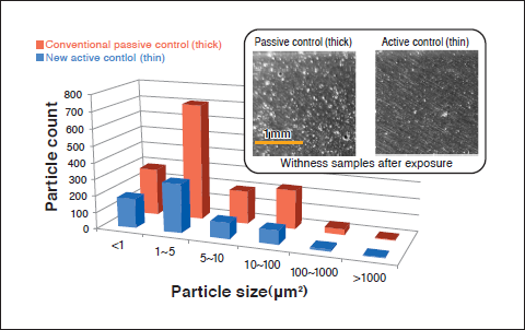
Fig. 5: Result of particle count for a conventional and new wiping mechanisms.
4. FAST ION REDUCTION AND CONVERSION EFFICIENCY ENHANCEMENT
It is known that EUV plasma, regardless of DPP or LPP, emits fast ions. In DPP plasma, it is well known from past Zpinch and plasma focus researches that energy of emitted ions can easily exceed the voltage applied to the electrodes. Such fast ions pass through the foil trap and sputter the reflective surface of the collector. A laser-triggered DPP utilizes a laser to create and control an initial plasma. It is essential for DPP source to control an initial plasma to make it match the electrical current to maximize energy transfer from the capacitor to EUV radiation. Heating of the plasma by the current can also be controlled by modifying parameters of the initial plasma. A conventional laser-triggered DPP uses only one laser beam to ignite the discharge. Once an electrode is irradiated by a laser, a laser-produced plasma translates vertically and horizontally, and causes electrical breakdown between the electrodes. Since the breakdown begins spontaneously when the laser-produced plasma approaches the other electrode, it is difficult to control the parameters of the initial plasma. In this work, we used two lasers to overcome this difficulty as shown in Fig. 6. The second laser is fired after the first laser with an appropriate time delay. In order to see the effect of this double-laser trigger, conversion efficiency and energy (speed) of emitted ions were measured.
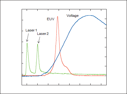
Fig. 6: Typical waveforms of laser, voltage and EUV emission.
Fig. 7 shows the typical waveforms of ion measured by a Faraday cup, derivative of the current (dI/dt), and EUV emission for a single-laser trigger (a) and double-laser trigger (b), respectively. In case of the single-laser trigger, a significant dip is seen in the current waveform. This is thought to be due to a strong compression of plasma causing rapid change of the impedance. Such a strong compression (implosion) is known to be a cause of very fast ion emission, which is indeed observed in the ion signal. When two lasers are used, a significant dip no longer appears in the current waveform, and thus ion signal appears much later in time.
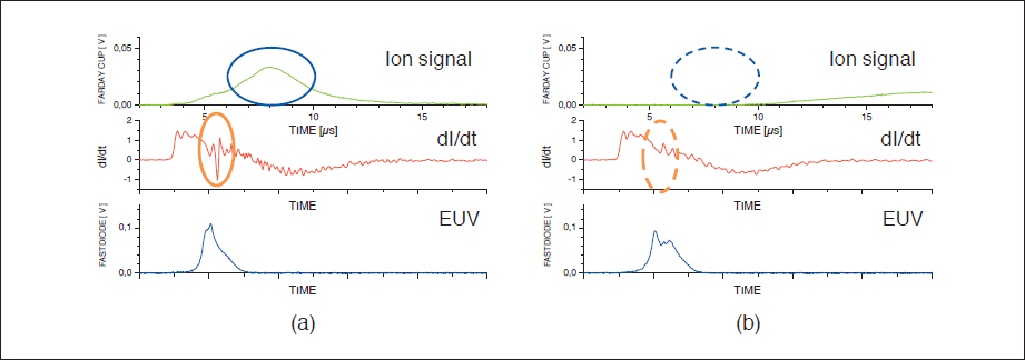
Fig. 7: Typical waveforms of ion signal, dI/dt and EUV for single-laser trigger (a) and double-laser trigger (b).
Fast ion charge measured by means of time-of- flight method as a function of time delay between two lasers is plotted in Fig. 8, as well as CE variation. Here, ion energy range of interest is between 10 to 250 keV. Amount of fast ion decreased with increasing time delay. At the optimum time delay, the mount of fast ions decreased by a factor of 5 compared to that of single-laser trigger, as low as 2.6 uC/sr. What is beneficial of this double-trigger method is that CE increases with time delay and becomes maximum when the amount of fast ions is minimum, resulting in CE improvement of 60%. It can be explained that a double-laser trigger changes the condition of initial plasma and thus coupling between discharge plasma and electrical circuit becomes better, leading to low fast ion emission and high CE simultaneously.
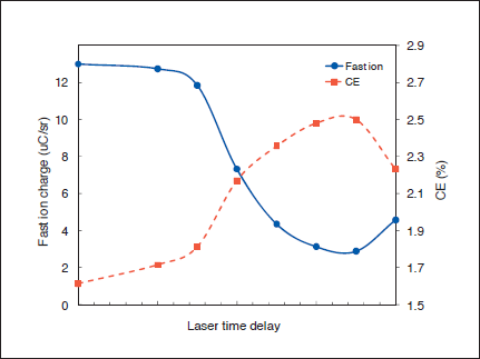
Fig. 8: Fast ion charge and CE variation as a function of laser time delay.
5. POWER SCALING RESULT
The technologies described above are very useful not only for lifetime improvement but also power scaling. In order to show the capability of a laser-triggered DPP source toward HVM level, a high-frequency and -power burst experiment was carried out. The experiment was done using a stand-alone source which has the same configuration as SoCoMo. Duty cycle of the experiment was 20% with 200-ms light-on period. Fig. 9 shows EUV power output from the plasma as a function of input power. EUV power increased linearly with input power at almost constant CE of approximately 2%. Finally, 1.5 kW/2πsr of in-band EUV radiation output was obtained at 74 kW, 18 kHz. At this power level, the source was running for approximately 1.5 hours.
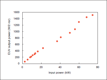
Fig. 9: EUV power scaling result up to 1.5 kW/2πsr.
6. SUMMARY
A new method of Sn layer control of the electrode surface, and double-laser trigger were researched and developed. As a result, the followings were derived.
- (1) Particle debris emitted from a laser-triggered DPP source was reduced by a factor of three.
- (2) Fast ions (10~250 keV) were reduced by a factor of five.
- (3) Conversion efficiency was increased by 60 %.
- (4) 1.5 kW/2πsr of in-band EUV radiation was obtained at input power of 74 kW in 20 % burst operation. Linear increase of EUV power as a function of input power was observed.
ACKNOWLEDGEMENT
This work was supported by NEDO, Japan. Authors would like to thank XTREME technologies GmbH, Germany for a lot of helpful technical discussions.