光技術情報誌「ライトエッジ」No.35(2011年8月発行)
2011.3 Proceedings of SPIE (SPIE Advanced Lithography 2011)
Regeneration of imprint molds using
vacuum ultraviolet light
Masashi Nakao*1), Masanori Yamaguchi2) and Shintaro Yabu2)
1) Nano ICT group, Kobe advanced ICT research center, National institute of information and communications technology, 588-2 Iwaoka, Iwaka-cho, Nishi-ku, Kobe, 651-2492, Japan
2) Project Promotion Department, Photon Process Bu, Ushio Inc. 1194 Sazuchi, Bessho-Cho, Himeji,671-0224, Japan
ABSTRACT
Etching characteristics of various resins by a vacuum ultraviolet (VUV, λ=172 nm) light have been examined under conditions of exposure time, substrate temperature, radiation distance and ambient oxygen concentration. The VUV light have used to clean the imprinted molds which are contaminated by organic substances such as ultraviolet-resins through many times of imprinting processes, and it has revealed that the VUV light has effectively regenerated the contaminated molds manufactured by quartz, silicon-carbide and nickel.
Keywords: Vacuum ultraviolet, Mold cleaning, Imprint lithography.
1. INTRODUCTION
Imprint-lithography is expected to become one of the next-generation nano-lithography techniques,1-3. The imprintlithography has been developing with the progress of the related technologies such as imprint-machines, mold release agents, ultraviolet (UV)-resins, and molds. On the other hand, cleaning method of the imprint-molds is left unsolved.
Repeatedly-imprinted molds should be cleaned for the next series of imprint-lithography process using an appropriate cleaning method which results in defect-free patterning.
There are several methods for imprint-mold cleaning. Organic solvents and strong acids are frequently used under the ultrasonic condition. However, they are sometime difficult to remove residuals completely from the grooves of concavoconvex-patterned surface, and both methods have environmental problem in time of liquid waste disposal. Dry cleaning methods by UV-ozone and O2-plasma are frequently used in the semiconductor process, because they are clean and easy. However, they are not effective in case of imprint-molds, which contain grooves and/or holes. Vacuum ultraviolet (VUV) is here adopted from the points of cleaning effectiveness and ecological technique.
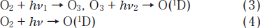
Cleaning mechanism of VUV light is briefly introduced. It consists of two steps; the first is decomposition of organic materials (CxHyOz) by VUV light with chemical bond dissociation energy of hν, and the second is oxidation by a singlet-oxygen, O(1D). Both reactions are shown by Equations (1) and (2), respectively.
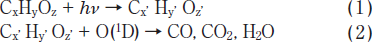
CxʼHyʼOzʼ represents chemical product of CxHyOz after breakage of chemical bonds, and the equations here are qualitatively shown. Then they are stoichiometrically incorrect. The singlet-oxygen is generated by following Equations of (3) and (4). The UV light by a mercury lamp generates the singletoxygen only by Eq. (3), where hν1 and hν2 are the energy of 185 nm and 254 nm light, respectively. In the case of VUV, both hν1 and hν2 are the same energy of 172nm light. In addition, VUV light also generates the singlet-oxygen directly from oxygen by Eq. (4). Therefore, the cleaning by VUV is more than ten-times effective than that by UV.
Establishment of mold-cleaning technology is ourfinal target .
*nakao_masashi@nict.go.jp; phone +81 78 969 2177; fax +81 78 969 2177; nict.go.jp
2. EXPERIMENTAL
The cleaning machine equipped with Xe* excimer type lamp, which was made by Ushio Inc.4, and which emited the light with wavelength of 172nm, had been originally developed. The machine can control a VUV-exposure time (tVUV), a substrate temperature (Tsub ), an ambient oxygen concentration (co), and a radiation distance (dRD). The cleaning procedure is as follows: 1st. A sampleis set on the plate at dRD, and the sample room is closed. 2nd. The sample plate is heated up to Tsub, and co is controlled by nitrogen flow rate into the sample room. 3rd. VUV with power (PVUV) is exposed on the sample for tVUV. The samples were observed by optical microscope, SEM and AFM. Thickness of resin layer was determined by ellipsometry measurements.
Four resins; TR-21B for UV-imprint lithography, polymethyl methacrylate(PMMA) for thermalimprint, ZEP for electron-beam lithography, and AZ1500 for photolithography, were used to measure the etching characteristics. Three imprint-molds; silicon-carbide(SiC) and Nickel(Ni) for thermal-imprint and quartz for UV-imprint, were used to examine the cleaning behaviors.
3. RESULTS
3.1 Deformation of grating pattern of UV-resin by VUV-exposure
We have successfully fabricated gratings on 3-inches GaAs wafer5, and nitrides substrate6 by UV-imprint technology, in order to apply them to distributed feedback lasers . Compared to electron-beam lithography, the imprint lithography offers the promise of high-throughput, large areas, and low cost. First, we apply VUV-light to deform the grating of UV- imprinted pattern, in order to remove residual resin or to change the grating shape. Figure 1 represents the AFM results of grating shape change of UV-imprinted resin (TR-21B) with VUV-exposure time. The exposure of VUV light was done under condition of Tsub=25□, dRD=3mm, co=21.9%. The grating shape changes gently toward planarization with exposure time. Grating height, corresponding to UV-resin thickness, changes linearly with the exposure time as shown in Figure 2. The etching rate of the UV-resin is around 17 nm/min.
Next we will measure the etching rate, or etching rate, by VUV-exposure under various condition for various resins.
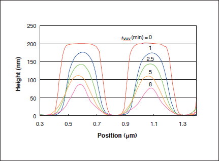
Figure.1: Deformation of grating shape of UV-imprinted resin by VUV-exposure.
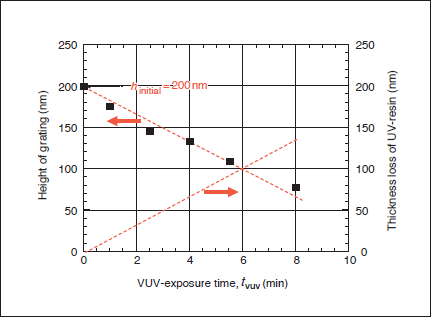
Figure.2: Change of gating height and UV-resin thickness versus VUV-exposure time.
3.2 Eching behavior of various resins by VUV-exposure
In order to investigate the effectivity of the developed VUV-exposure machine, various resins have been examined. Figure 3 shows dependence of the VUV-exposure time on the amount of thickness loss (= etching amount) for various resins. VUVexposure condition is Tsub=25°C, co=20.9%, and PVUV=10mW/cm2. Etching rates are 3.2, 9.2, 17.0, and 29.4nm/min for AZ1500, ZEP, TR-21B(polymer), and PMMA, respectively. The order of the rate is same as the wellknown case of UV-ozone ashing. The results of TR-21B(monomer), which represents before UV-imprint, are plotted as a reference. Imprintrelated resins, i.e. PMMA and TB- 21B possess relatively high etching rate, which is positive meaning from the point of mold-cleaning. The etching rates difference of about one-order magnitude between PMMA and AZ1500 may be useful in case of pattern transferring from AZ1500 to PMMA by VUV-light.
Figure 4 shows temperature dependence of thickness loss of ZEP resin under irradiation of VUV light. VUV-exposure condition is co = 20.9%, and PVUV= 10mW/cm2. The results for five VUV- exposure time, i.e. 4, 8, 12, 16 and 20 minutes are presented in the Figure 4. The higher substrate temperature is, the more effective etching process becomes. VUV- etching at 100°C is ca. 3-times effective, as compared at room temperature.
Figure 5 shows the dependence of VUV-exposure distance on the amount of thickness loss for ZEP. VUV- exposure condition is tVUV= 4 min, co = 20.9%, and PVUV = 10 mW/cm2. The less dRD is, the more VUV reaches to the sample surface, and the more amount of thickness loss becomes, because the singlet-oxygen generated in the vicinity of sample surface decomposes resins efficiently. The amount of attainable VUV to the sample surface is influenced by the ambient oxygen concentration. Next, the effect of oxygen concentration was examined for ZEP at different distances as shown in Figure 6. VUV-exposure condition is Tsub= 50°C, tVUV= 3 min, dRD= 3 mm, and PVUV= 10 mW/cm2. Peak position shifts from 8% to 14% of oxygen concentration with decreasing radiation distance of 4 mm to 1 mm. The reason for these peaks is understood under consideration of generation amount of singlet-oxygen in the sample vicinity. That is, under some distance condition (3 mm in case of Fig. 5) the singlet-oxygen generating sample surface increases with increase of oxygen concentration. After reaching maximum point, further increase of oxygen concentration brings decrease of singlet-oxygen concentration because of strong absorption of VUV by oxygen before reaching to sample surface. As a result, etching rate becomes maximum at around 8% of oxygen concentration at 4 mm.
The results obtained above are benefit for mold-cleaning.
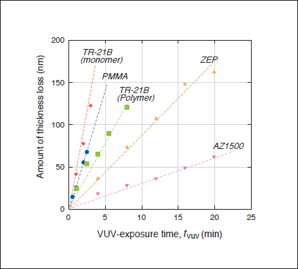
Figure.3: Thickness loss of various resins by vuv-exposure.
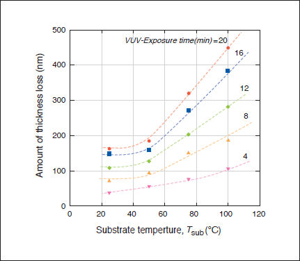
Figure.4: Effect of Substrate temperature on thickness of ZEP by VUV-exposure.
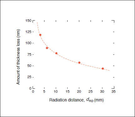
Figure.5: Effect of radiation distance on thickness of ZEP by VUV-exposure.
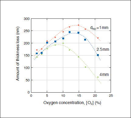
Figure.6: Effect of ambient oxygen concentration on thickness of ZEP by VUV-exposure.
3.3 Imprint-molds cleaning
Successive cleaning results of imprint-molds by VUV exposure are shown in Figures 7, 8 and 9. The molds examined here are strongly contaminated by the imprint-resins. Figure 7(A) and (B) show pictures of optical microscope before and after 5-minutes VUV exposure. This mold is SiC with 100-200 nm L&S patterns and 150 nm in depth,7. VUV condition is Tsub=100°C, dRD=3mm, co=8%, and PVUV=10 mW/cm2. If considered from the picture of Fig. 7(B), it is enough and succeeded to clean the SiC mold. However, it remains residual resin in the SEM picture as shown in Fig. 7(c), which is observed same sample of Fig. 7(B). It indicates that VUV exposure for 5 minutes is not enough under present VUV exposure conditions. After additional 5 minutes VUV- exposure, the SiC-mold was observed by SEM, and no attached resin was seen on the SiC-mold surface, as shown in Fig. 7(D). In the case of thermal imprint using SiC-mold and PMMA-resin pair, 10 minutes VUV-exposure is very effective for reproduction of contaminated molds.
Figure 8 shows the cleaning result of quartz mold, which contains attached UV resin, TR-21B. The quartz consists of 150-300nm L&S patterns with depth of ca. 250nm5. The UV-imprint resin is difficult to remove from the quartz-mold by using organic solvents, such as acetone and alcohol, which are generally used to wash out various resins. VUV condition is Tsub=25°C, dRD= 2mm, co=20.9%, and PVUV = 100 mW/cm2. Figure 8 (A), (B), and (c) show pictures of optical microscope taken before VUV exposure, and after 5 and 10 minutes exposure, respectively. Strongly attached UV-imprint resins are removed by 5 minutes VUV-exposure, and residual UV resins in the grooves are completely removed from the quartz-mold as shown in Fig. 8(c). It is difficult to observe quartz by SEM. However, it is obvious that VUV-exposure is very effective for reproduction of quartz-molds, reproduction of contaminated molds.
Figure 9 shows the cleaning result of Nickel mold, which contains PMMA. VUV condition is Tsub= 100°C, dRD= 4 mm, co=8%, and PVUV= 100 mW/cm2. Figure 9 (A) and (B) show pictures of optical microscope taken before VUV exposure, and after 10 minutes exposure, respectively. Regeneration of Nickel mold is successful.
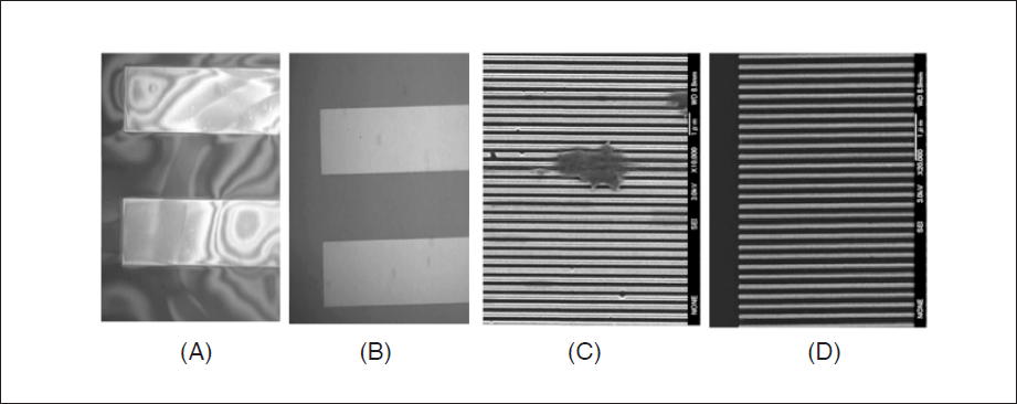
Figure.7: Cleaning results of sic mold
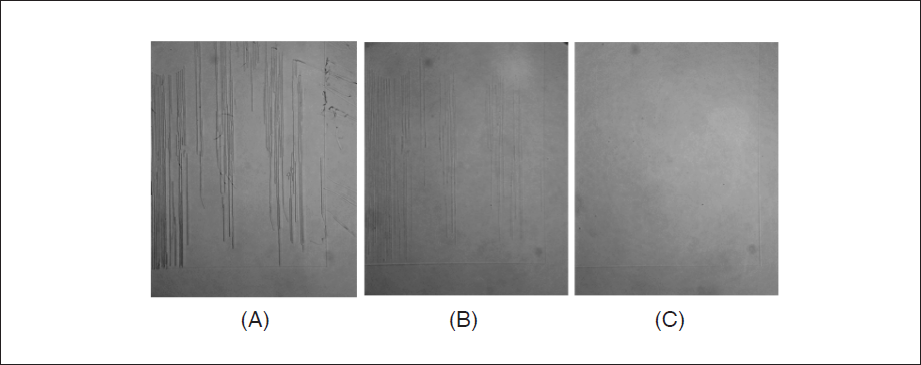
Figure.8: Cleaning results of quartz mold.
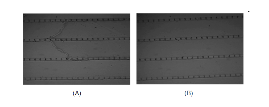
Figure.9 : Cleaning results of Nickel mold.
4. CONCLUSION
The cleaning treatment of contaminated resins on the concavoconvex-substrates by exposure of vacuum ultraviolet (VUV) proves very useful not only for the imprint resins but also for various resins. Effective etching of resins is induced by long-time-, highsubstrate-temperature- and short-distance- VUV exposure. In addition, optimum oxygen concentration exists. The cleaning technology for imprint-molds is successfully established.
ACKNOWLEDGEMENTS
A part of this research was supported by Grantsin-Aid for Scientific Research, MEXT (No. 20200028) and JST/CREST.