光技術情報誌「ライトエッジ」No.16
4th International Symposium on 193nm Lithography
(1999年3月)
ArF Excimer Laser for 193 nm Lithography
Takashi Saito, Ken-ichi Mitsuhashi, Motohiro Arai,
Kyouhei Seki, Tatsushi Igarashi, and Kazuaki Hotta
USHIO Research Institute of Technology Inc.
5-2-4 Tokodai, Tukuba, Ibaraki, Japan
Telephone:+81-298-47-9072 Fax:+81-298-47-9076
A line-narrowed ArF excimer laser are being developed as a light source for 193 nm lighography using a refractive lens system. The system is required a narrow spectral bandwidth, high laser output stability and long lifetime. In this laser, we present a newly developed sub-picometer ArF excimer laser for lithography.
The prototype laser, as shown in this paper, utilizes an all solid state pulse power modulator with 2-stage magnetic pulse compressors. A barrier discharge excimer lamp technology 1) developed by USHIO is adopted as a pre-ionization method. The materials that constitute this laser are carefully selected to prevent the impurity generation. A long gas life time of over 4×10⁷ shots has been confirmed in a broad-band operation.
The line-narrowing optics in this laser consists of a combination of prism beam expanders and a grating. Figure 1 shows a spectral profile measured by an etalon system with a FSR of 6 pm and a reflection finesse of about 30. Figure 2 shows an ingegrated energy distribution. More than 5 mJ of pulses with of below 0.6 pm FWHM and 95% of the spectral energy lying within a 2 pm were obtained. The laser output stability and the spectral stability will be also presented.
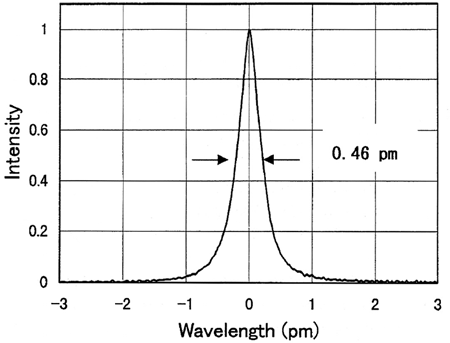
Fig.1 Spectral bandwidth measured by etalon system with a free spectral range of 6 pm
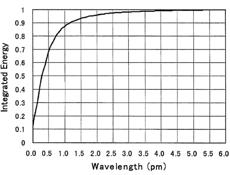
Fig.2 Integrated ene rgy Distribution
参考資料
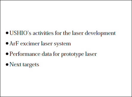
Table1.Outline
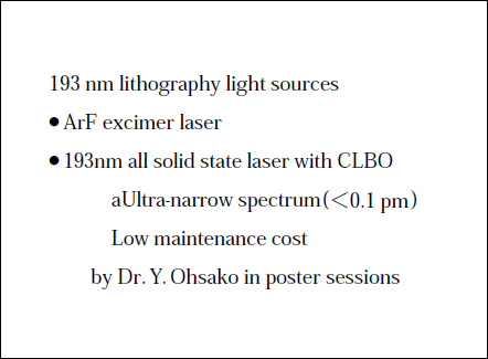
Table2. USHIO's activities
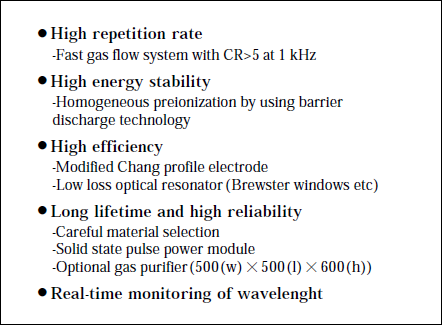
Table3. Characteristics of the ArF excimer laser system
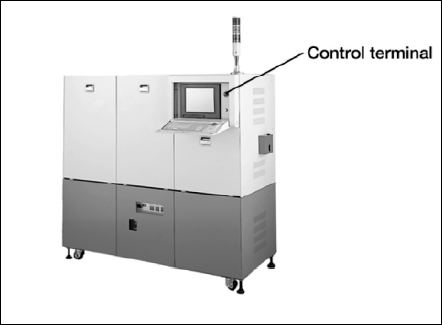
Fig.3 Photograph of ArF excimer laser system
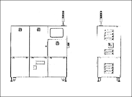
Fig.4 Schematic view of ArF excimer laser system
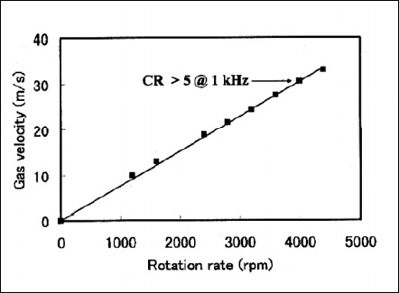
Fig.5 Gas flow velocity
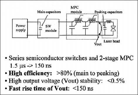
Fig.6 Solid state pulse power module
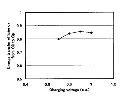
Fig.7 Characteristics of SSPPM
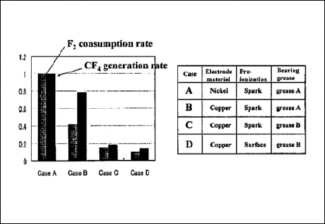
Fig.8 Material selection(chamber)
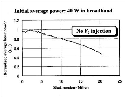
Fig.9 Gas lifetime test at 1 kHz in constant voltage mode
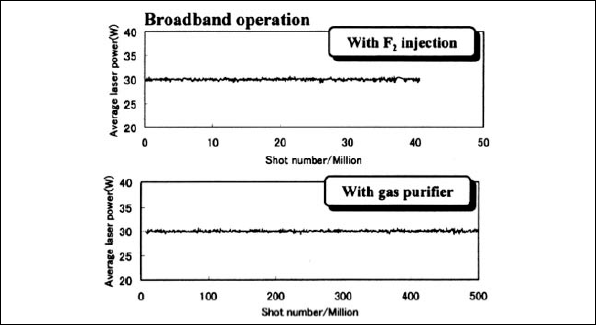
Fig.10 Gas lifetime test at 1 kHz in stabilized power mode
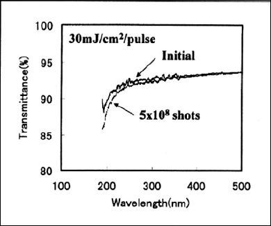
Fig.11 Transmittance of CaF2 windows
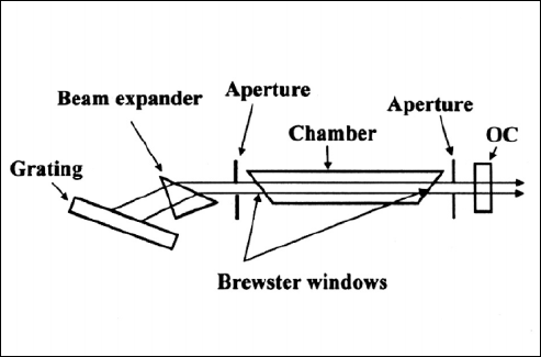
Fig.12 Optics module
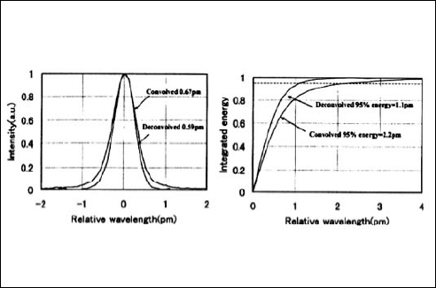
Fig.13 Spectrum of the whole laser beam
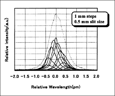
Fig.14 Sepctra of different portions of the laser beams
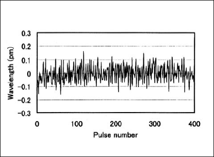
Fig.15 Wavelength stability
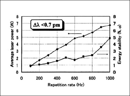
Fig.16 Average laser output power and stability
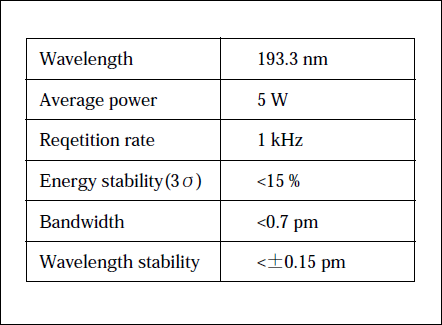
Table4. Specifications of our prototype laser
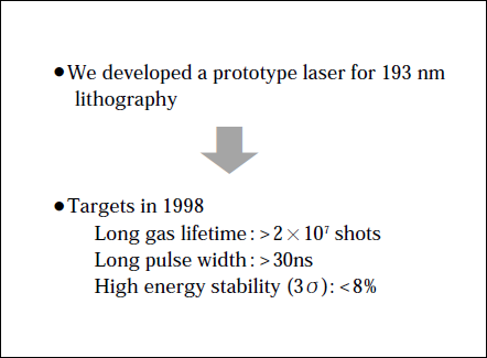
Table 5. Summary
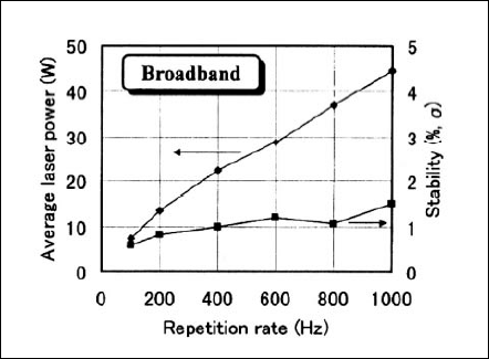
Fig.17 Average laser power and stability
論文を探す
ウシオ社員の学会発表論文、投稿論文をご紹介します。
(1999年03月)