IAS(IEEE Industry application society)2004 Annual Meeting
(2004年10月)
Recent progress on UV lamps for industries
Yukihiro Morimoto, Taku Sumitomo, Masaki Yoshioka, Tetsu Takemura
R&D Center, Lamp company
Ushio Inc.
1194 Sazuchi, Bessyo-cho, Himeji 6710224, Japan
Abstract
Radiation in nature so called daylight dominates only the small region in all wavelengths. UV-ray is located at higher energy region than that of daylight and induces some reactions, which is caused by an act as energetic particles. UV lamps with specific wavelength are controllable for selected reaction in the limited area and the time. They are tried in laboratories at first and applied in industrial plants with great progress of lamp components and their electric circuits. This article reviews the recent progress of industrial discharge lamps radiating UV, VUV, or other specialized wavelength.
Keywords; ultraviolet-ray; Super-high pressure mercury lamp; flash lamp; excimer lamp
I. Introduction
UV lamps are used for various purposes in the industries of Electronics, Mechatoronics, Display, Chemical, Bio, and Communications. Because of their high luminance or illuminance, it is effective to use the UV lamps especially in the case that a large fluence of UV photons affect as energetic particles and promote the reactions, so-called photochemical reaction, or processes at the surface of matters. Although the working mechanisms or the theories of the discharge lamps are universal and unchangeable, the properties of the lamp itself have remarkably changed to be situated to the specific purposes of the specific industries. This article shows four unique topics of lamps used for recent demand from the industries.
It is well known that G-line and/or I-line radiated from the super-high pressure mercury (Hg) lamp are useful and used for photo-lithography process and inspection process in the semiconductor manufacturing process, and the stable qualities of these lines’width and intensities have been changed to meet the higher through-up requirement of the manufacturing process. In addition, these days, it was recognized that the illumination with pulsed light was an advantageous way in the heating and annealing processes of the silicon wafer. As a result, the flash lamp, as well as a KrF laser, is adapted to this process for electrical activation and rearrangement of the crystal structure in the ionimplanted layer of the surface. Another application of the UV lamps is for bacterium by irradiating 254 nm-line from a lowpressure mercury lamp, but more intense and conventional VUV light was realized by a Xe excimer lamp in this decade, which has been applied for more effective treatment of water or dry-cleaning process of liquid crystal products. On the other hand, the super-high pressure Hg lamp is utilized as a light source of a projector system: the color rendering properties were improved by increasing Hg pressure up to more than 150 atm during operation to increase the radiation in wavelength region >500nm.
II. Super-high pressure mercury lamp
A super-high pressure, dc short arc Hg lamp [1] is used in industries to supply energy of light from visible to especially UV and deep UV. The small arc size of the lamp has an advantage as is adaptable for the optical system of micro fabrication equipment.
A. Emission spectra
An arc is formed at the center of the lamp in the fillgases of mercury vapor and a rare gas. Line spectra and continuum spectra are emitted from the arc plasma, that depends upon the operating pressure of lamp.
Fig.1 shows a spectral distribution of a lamp used in semi-conductor lithography. The g-, h-, i-lines are observed at 436, 405 and 365 nm in wavelength, respectively. In Fig.2 the spectral distributions of the lamp designed to emit stronger g-, and h-lines are shown. Lamps of this type are suitable for LCD exposures processes.
An Hg atom excited by the electron emitted from a cathode will eventually lose its energy through transition to ground state or metastable state. The energy difference between the states is emitted as a line spectrum. The energy level diagram of Hg in Fig.3 shows that g-, h- and i-line has a few lines in neighbor. The Continuum emission occurs by recombination of mercury ions with free electrons. The emitted energy, hence the wavelength is expressed as a function of the kinetic energy of an electron and the ionization energy of mercury.
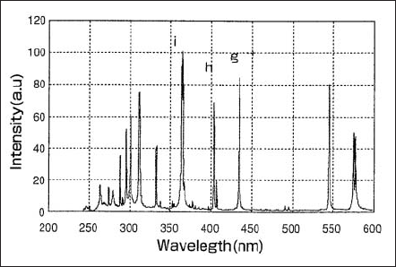
Figure 1. Spectral distribution of a lamp used in semiconductor
lithography exposure.
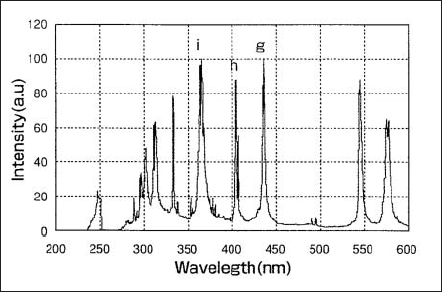
Figure 2. Spectral distribution of a lamp used for LCD lithography process.
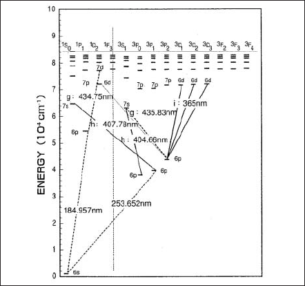
Figure 3. Energy level diagram of mercury.
B. Features
To maintain the intensity of light output more than a guaranteed period, various considerations have to be made to optimize the lamp parameters concerning with the structure and the properties of a lamp.
A lamp structure in which the cathode and anode are placed so as the arc is formed at the center of the silica glass bulb. As exposed to the flux of electrons supplied by the cathode, the anode temperature is much higher than that of cathode. The cathode material has been optimized to maintain an effective emission of thermal electron. The rare gas filled together with mercury is usually chosen among argon, krypton, and xenon considering the properties such as starting characteristics and lifetime. Silica glass bulb has a high transmissivity from UV to IR region, and an excellent strength at high temperature enabling to contain a high-pressure gasmixture at high temperature in lamp operation.
There are four important properties for the super-high pressure Hg lamp: the electrical property, thermal property, optical property and the lifetime. The electrical properties are described by breakdown voltage, transitional current during the warm-up, and the voltage and current in steady burning. Under steady operation at constant power input, the lamp voltage increases and the current decreases as the distance between cathode and anode increases or Hg pressure increases. Regarding the thermal properties the temperature of the lamp bulb must be kept in the designated range since it is important for the light output performance determined by Hg pressure. Among optical properties the spectral distribution has been described in section A. An example of the angular distribution of radiation from the lamp is shown in Fig.4 for the case that the lamp is burning anode upside. Fig.5 shows a quantity corresponding to the radiant intensity of the arc observed when the arc image is projected along a line parallel to a lamp axis. Maximum radiant intensity is obtained at nearby cathode tip and gradually decreases toward anode. Lifetime property is given by the decrease of the illuminance and the degradation of the silica glass bulb. The former is mainly caused due to the increase of evaporation and deposition of electrode materials at the inner surface of the bulb, and light scattering takes place, accordingly the transmissivity decreases.
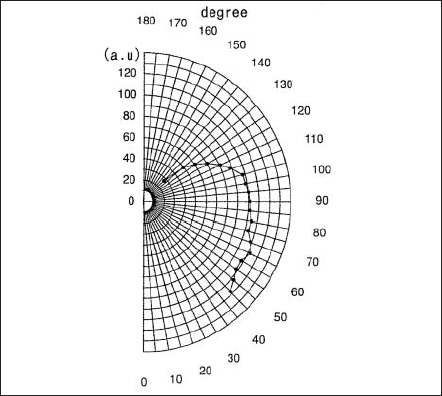
Figure 4. Angular distribution of radiation from an arc with anode placed upside.
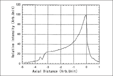
Figure 5.
C. Usage
The most of the application of super-high pressure Hg lamp is as a light source for exposure in the manufacturing processes of semiconductor, liquid crystal panel, PDP (Plasma Display Panel) and print circuit board (PCB).
After the lithography technology by g-line was developed in early 1980s, i-line became to be used in the frontier as the line width became thinner. Owing to the progress of illumination technology on the step-and-repeat method it was used to depict 0.3µm-line in width. Lamps for g- and i-lines radiation have been used in suitable processes, in mix and match together with lasers. Application to LCD lithography requires higher power lamps as glass plate becomes larger. Light ranging from g- to i-lines is used in the exposure processes of TFT type LCD, LCD color filters, PDP, and PCB.
These days, in application to semiconductor processes higher power lamp larger than 3 kW has become to be used as the silicon wafer becomes larger. Also in LCD exposure usage more than 5 kW lamps have been used as the LCD glass plate becomes larger.
III. Super-high pressure Hg lamp for projectors
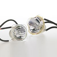
The high pressure or super-high pressure Hg lamps have been utilized as an UV light source radiating specific line spectra and operating at the pressure of Hg about 40 atm at most for almost all the cases of the industrial applications, as described in the former section. A projector was invented and widespread in the world as so-called“data projector”in this decade. The super-high pressure (P>150 atm) Hg lamps are generally used for their light source, and these days, the tendency of downsizing of the projectors requires more compact shape, longer lifetime, and higher liabilities to the lamp, and one of the solutions is to increase the Hg pressure during operation.
The spectral features of the super high pressure Hg lamp was confirmed by Elenbaas in 1936 at the operating pressure more than 150 atm and reported that the luminous efficacy achieved to 70 lm/W [2]. Fifty years later, the Hg lamp was reminded again for the projection light because of its usefulness properties: the high luminous efficacy and the high luminance. NSH is Ushio’s brand for the projector lamp and commercially available in line-up from 100W to 310W. The features of NSH lamp are not only the high luminous efficacy and luminance but also little spectral changes with longoperation time because the spectra are simply determined by atomic Hg and/or molecular Hgs in form, not by other metal compound like a metal-halide lamp. Addition of mercury-halogen compound (HgBr2) prevents the NSH lamp from blackening by halogen cycle, which allows lifetime elongation without luminous flux decrease. As a result, the NSH lamp took the place of a metal halide lamp for the projectors.
Fig. 6 shows the changes of Hg spectra as a parameter of the spatial density of mercury filled-in. Hiramoto explained the spectral features of the high pressure Hg discharges as follows [3]. The line spectra are resolved at 407,436,546,578 nm, which is due to the transition between discrete excitation energy level. These line spectra broaden with increasing intermolecular force due to the Hg pressure increase; i.e. the radiation bands of molecular form in Hg2 are resolved at 420, 433, 451 and 464 nm. The continuum spectra in the wavelength more than 500 nm are mainly due to bremsstrahlung radiation of electrons at Hg atoms. Since the NSH lamps operate at more than 200 atm, spectrum in red region is good enough to illuminate the projection image in color. The higher pressure is also necessary to maintain high luminous efficacy for the shorter arc gap lamp, operating without losses at the electrode as much as possible. These electrode losses should be caused by the emission of electrons and bombardment of the electrode tip. Higher pressure of Hg in plasma forces the lamp voltage to be higher, which leads to a relatively low lamp current and suppress the electrode losses.
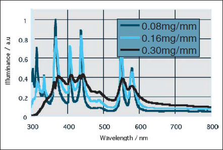
Figure 6. Spectrum changes depending upon the pressure of mercury filled.
One of the determination factors for the lifetime is the degradation of luminous flux caused by the bulb blackening. Low electrode losses help to minimize the evaporation of the electrode because of low operation temperature at the electrode tip. Another engineering solution to the blackening is the addition of bromine (Br) to induce“halogen cycle”. Although the halogen cycle is basically the same as the halogen lamp, the temperature range of operation in the NSH lamp is quite different and higher than the halogen lamp; the head of electrodes melts during operation ( T>3650K ) and the inner bulb temperature should be kept to maintain the Hg pressure, i.e. 880 ºC for 15 MPa or 940 ºC for 20 MPa. Another role of halogen additives is to prevent the crystallization at the inner surface of SiO2 glass bulb and the growth, which lead to not only the degradation of luminous flux but also the lamp fracture. This devitrification phenomenon is depressed by doses, which is a few more halogen addition for the halogen cycle, and the lifetime property of the lamp could be improved successfully [4].
The durability to the pressure more than 200 atm is extremely required to the bulb and the sealing part of NSH lamp under operation. The structural features resisting to the high pressure are its thicker bulb wall and smooth form with no exhaust pipe on the envelope. In the lamp manufacturing process, as a result, two of the electrode mount, Hg, halogen compounds (HgBr2) and starting gases (Ar) are incorporated in one closed envelope tube before sealing.
A sealing between silica glass and the electric-feed metal has been established by a molybdenum (Mo) ribbon. Here, there are two factors to determine the sealing strength: the structural shape and the adhesiveness of the SiO2 -Mo ribbon interface. As shown in Fig. 7, thewelding portion of the Mo ribbon is curved in form to fit to the end of electrode to minimize stress generation in the glass. In this way, the separation of the SiO2 -Mo ribbon interface was quite restrained as compared to the flat ribbon cases. It was good to make use of an Y2O3-CeO2 doped Mo ribbon (MY-ESS, Plansee Aktiengesellschaft) to obtain stronger adhesiveness at the interface [5]. However, that was not enough for the NSH lamp, because the impurities like Ar, Hg, and Br for the SiO2 and/or Mo may exist in the interface and weaken the force during high temperature sealing process of the closed tube. To avoid the contaminant at the interface and unexpected separation, or in worst case, fracture of the lamp during operation, the Mo ribbon may be coated by a few hundred nanometers of SiO2 film after the treatment for elimination of native oxides and/or organic compounds by hydrogen gasses [6]. In the conventional burner seal, the vapor of SiO2 from the envelope deposits on the Mo ribbon by few ten nanometers (depending on the atmosphere inside the tube), and the interface is formed when the seal portion of the envelope was shrunken and touched to the ribbon. On the other hand, the interface of Mo-SiO2 layer formed by coating method is considered to be dense, very clean and strongly bonded to each other.
There are other inventions to form other metal-oxide coating layer on the Mo ribbons. For example, Zirconium oxide film is act as a barrier to alkaline elements that are existed in the envelope SiO2 glass and moved to the interface by electrophoretic migration during operation [7].
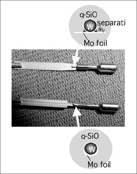
Figure 7. Comparison of the mount structure for NSH lamps.
IV. Excimer lamp
The dry cleaning technique was introduced in 1980s in accordance with the growth of Liquid Crystal Display (LCD) industry. It is an easy process to clean the surface by UV radiation under atmosphere at low temperature, and have been adopted in more factories. At the beginning, the low pressure mercury discharge lamps were used as UV radiation source. Higher power mercury lamps improve the production efficiency, but their heat yields the surface damage. A new UV radiation source was needed taking into account of mercury free. We developed“Excimer Lamp”as a new UV radiation source in 1990s. It removed the low pressure mercury lamp’s defects and has been widely accepted in manufacturing process, such as preliminary washing before wet process and film fabrication process in LCD factories.
A. Variety of Excimer lamps
Conventional lamps radiate the emission due to the atom transition, molecular transition, or recombination, but excimer lamps are unique in emission from excited dimmer, or excimer. We put them to practical use with use of dielectric barrier discharge. Barrier discharge has been commonly used as ozonizer for a long time [8] and was known to radiate rare gas excimer emission [9]. Barrier discharge can establish non-equilibrium equilibrium discharge relatively easily at almost atmospheric pressure. These features are desirable for excimer production. Barrier discharge type excimer lamp has more features that a) no electrodes inside the tube broaden gas selection, b) free tube design, c) high efficiency.
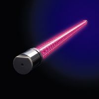
A typical barrier discharge excimer lamp is shown in Fig.8. Outer cylindrical tube and inner one are arranged concentrically and both ends are closed. One electrode is set inside surface of the inner tube and the other electrode is set outside surface of the outer tube. High frequency electric power from tens Hz to a few MHz is supplied to both electrodes. Barrier discharge is generated between both tubes and excimer radiation goes through quartz outer tube and mesh shaped outer electrode.
Xenon excimer is formed and emits as follow mechanism. Xenon atom is excited and ionized by high energy electron in discharge. Excited xenon atom and ground state xenon atoms produce xenon excimer molecules by three-body reaction. Xenon excimer does not interact with the weakly bound ground state, but decays by radiation. The spectrum is dominated by second xenon excimer continuum emission band at 172nm with 14nm half bandwidth.
Excimer is also formed in discharge of rare gas and halide gas complexes. Argon, krypton, and xenon gas discharge radiate 126nm (Ar2 *), 146nm (Kr2 *), and 172nm (Xe2 *) emission respectively. Chlorine gas mixed with krypton or xenon gas discharge radiates 222nm (KrCl*) or 308nm (XeCl*) respectively. Those excimer lamps are on market as single band UV emission source shown in Fig.9.
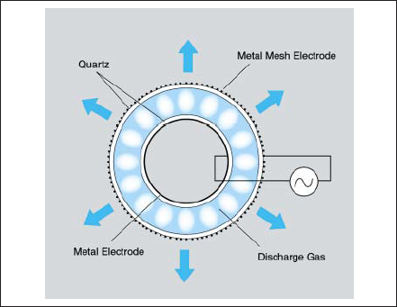
Figure 8. Example of dielectric barrier discharge lamp.
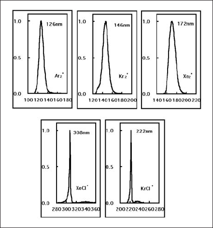
Figure 9. Emission spectra of various excimer lamps.
B. Excimer lamp unit
Some excimer lamps are arranged in parallel to achieve large area irradiation. Fig. 10 shows a typical excimer lamp unit. Each lamp is bedded in water-cooled lamp bracket. Light reflectors between the lamps increase forward radiation and improve the uniformity of light intensity distribution. Lamp unit is filled with dry nitrogen gas. Dry nitrogen gas does not absorb 172nm-light and helps lamp electrodes and reflectors from oxidation. A large area quartz window keeps dry nitrogen gas inside the lamp unit and permits 172nm to emit forward. An example of commercially availablelamp unit is shown in Fig.11.
Excimer lamps have many features, a) shorter wavelength emission, b) single band emission, c) high efficiency, d) instant and repetition ignition, e) less heat radiation, f) free burning direction, g) flexible tube design. Instant ignition brings lower energy consumption and longer lifetime. Less heat radiation encourages low temperature photochemical process.
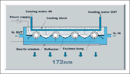
Figure 10. Schematic view of lamp unit.
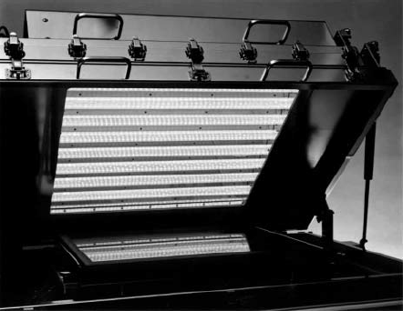
Figure 11. Photograph of excimer lamp unit.
C. Industrial application of excimer lamps
One of the dry cleaning processes is photo-cleaning process, such as UV/O3 cleaning, with ozone and UV effects. Low pressure mercury discharge lamp emits 185nm and 254nm. Oxygen absorbs 185nm emission and turns to be ozone. 254nm emission is absorbed by ozone and activated oxygen atom (O1D) is formed. 185nm emission itself decomposes most molecular bonds in organic compounds. In consequence, organic compounds evaporate with transforming into water vapor and carbon dioxides gas [10] as shown in Fig. 12.
172nm emission from xenon excimer lamp can produce activated oxygen directly [11], [12] and oxygen absorbs it by twenty times more than 185nm. As a result, activated oxygen is produced at higher concentration. 172nm emission has more photon energy to decompose the bonds than 185nm. Fig. 13 shows the result of LCD glass substrate cleaning with low pressure mercury discharge lamp and xenon excimer lamp. Contact angle of deionized water is well known as a method to estimate contaminants cleaning ability. Excimer lamp can deal with by a few times effective than low pressure mercury lamp.
172nm excimer lamp cleaning is also applied in organic electroluminescence display (OELD) manufacture process. Emissive organic layer with low molecule is weak for moisture and decreases its intensity rapidly. OELD’s cover must be sealed by adhesive cement so that OELD is blocked off from air completely. Its contact surface condition is very important for quality. Photo cleaning of organic compounds on the contact surface improves the adhesion strength and life reliability. It is proved the effectiveness of 172nm photo cleaning process. We introduce a new wafer cleaning technique with ionic or ozonic water irradiated by excimer lamps, so called“functional water”. 172nm excimer emission improves hydrophilia of wafer surface against ionic water and ozonic water. It also gives additional energy for spread water over the wafer surface, and promotes reaction speed. This effect is proved in the KrF resist removal [13].
High oxidation of the organic compounds on the plastic surface forms carbonyl group (>C=O) or carboxyl group (-COOH), and this phenomenon is recognized by XPS evaluation [14]. These polar groups make the ink wettable and adhesion stronger.
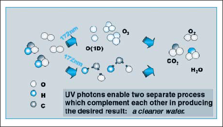
Figure 12. Surface cleaning echanism by 172nm excimer radiation.
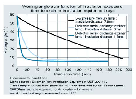
Figure 13. Surface cleaning results of low pressure mercury lamp and 172nm xenon excimer lamp.
V. Flash lamp
A flashlamp is a gas discharge light source designed to produce pulsed instantaneous radiation. The application of this lamp is widely known as strobes for cameras, blackout lights for aero system and obstruction lights at night. Moreover, from a view of an industrial use, this lamp is in widespread use of pump sources for solidstate lasers, and of heat sources for toner fixing of copying machines.
Recently a flashlamp has been rapidly noticed as a solution of a thermal treatment of semiconductor manufacturing process. In this section, a basic concept of a flashlamp and its feature including a new application of the thermal treatment will be mainly given.
A. Principle of Radiation
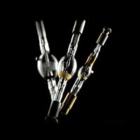
A flashlamp belongs to a type of DC discharge lamps and has an anode and a cathode inside the bulb. Xenon or krypton gas of specified volume is filled in the bulb.
In a typical operating circuit, an inductor is serially connected to an electrode. A capacitor, which is defined to store electrical energy, is also connected in parallel with the lamp electrodes. Once electrical energy is charged to the capacitor from a high voltage charger, the capacitor instantaneously discharges electrical energy via electrodes into pre-ionized gas that is build up by external trigger in advance. Profiles of the discharge current and voltage can be precisely calculated from inductance of the inductor, capacitance of the capacitor and specific lamp impedance.
The pre-ionized gas grows to thermal plasma of which temperature is approximately 8000-10000K. It is not simple to characterize the spectral output of a flashlamp. The thermal plasma emits radiant energy over extremely wide range of wavelengths from far infrared to vacuum ultraviolet. Radiation spectrum consists of line and continuum components. These components mainly result from three physical phenomena, i.e., Boundbound transition, Free-bound transition, and Free-free transition.
The line spectra correspond to bound-bound transition between the bound energy states of the gas atoms and ions. The continuum radiation results from energy release from recombination from gas ions trapping electrons into bound states (free-bound transition) and freefree transition called bremsstrahlung radiation from electron decelerated by complicated local electric field during collision with ions in thermal plasma. Xenon and krypton are normally chosen as the filling gases for flashlamps. Krypton provides a better match to Nd : YAG than xenon to select a pump source for solid sate lasers.
B. Feature
A flashlamp is capable of providing much higher peak power than that of continuous operation sources. Electrical input power range may be varied from 10-2 to 105 joules per pulse, pulse duration from 1µs to 104µs, and pulse repetition rate from single shot to several kHz. Converted peak powers can attain MW order.
Flashlamps come in variety of sizes and shapes including linear, helical and U-shaped and so on. Wide area radiation at once can be realized by the combination of an array of multiple linear flashlamps and optical reflectors.
C. Application
Recently, a flashlamp moves into the highlight with its feature in semiconductor industry. Ultra shallow junction (USJ) with low resistance is required to improve short channel effects in sub 50 nm gate length MOSFETs, and is particularly important for P-MOSFETs, which is shown in Fig. 14. [15]
According to the 2001 ITRS roadmap, source/drain extensions shallower than 19 nm will be required for 70 nm technology node [16]. However, the current rapid thermal annealing (RTA) tool by using halogen lamps will certainly encounter the trade-off between thermal diffusion of dopant atoms and electrical activation, which is limited by solid solubility. The annealing method also needs to satisfy the junction leakage specification, that is, sufficiently low defect density. [17]
In order to reduce the annealing time at high temperatemperatures, laser-annealing method is one possibility for the purpose. However, from the view of CoO, driving lasers are too expensive as an intense and short-pulsed radiation source.
Flashlamp annealing (FLA) method has been developed [17, 18] recently. FLA can raise the electrical activity and can control the diffusion of impurities in wafers. Moreover, FLA provides relatively modest cost.
Fig. 15 shows the typical emission spectra of a xenon flash lamp and a tungsten halogen lamp, and the absorption characteristics of crystal silicon. Whereas the emission intensity of the tungsten halogen lamp is high at longer wavelengths, the emission spectrum distribution of the xenon flash lamp is white light and the intensity is high in the broad visible spectral region, particularly at wavelength in the range from 300 to 600 nm. Since the rate of photon absorption of crystal silicon is high in the shorter wavelength region, the radiant energy of the xenon flash lamp can be more efficiently absorbed in silicon than that of the tungsten halogen lamp.
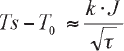
A following relation can estimate the surface temperature Ts of a substrate after irradiating.
where T0 is initial temperature of the substrate, k is a constant, J indicates the effective energy which was absorbed by the substrate, and τ indicates a time duration of the irradiation. From this relation, higher surface temperature can be attained by more irradiation energy or shorter pulse duration time.
Fig. 16 shows the typical temperature profiles of the current spike RTA and FLA by comparison. In the case of spike RTA, in which the peak temperature is 1050ºC, the total time of ramp-up and ramp-down (from 900ºC to 1050ºC and from 1050ºC to 900ºC) is about 3 s. On the other hand, FLA can reduce the annealing time to the millisecond range [18].
Fig. 17 shows the sheet resistance and the junction depth (xj@5x1018cm-3) map for RTA and FLA. The active concentration limit for FLA is much higher than that for RTA. RTA cannot be extended beyond the 90 nm technology node. On the other hand, FLA can satisfy the requirements of 70 nm technology node.
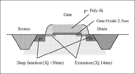
Figure 14. Schematic cross sectional view of P-CMOS.
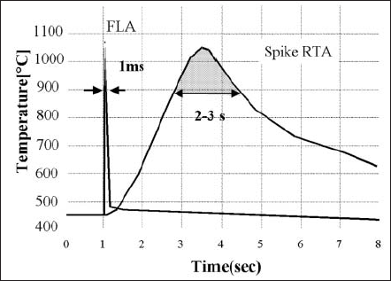
Figure 15. Temperature profiles of spike RTA and FLA
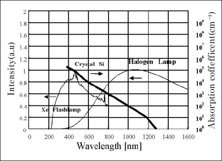
Figure 16. Emission spectra of Xe flashlamp and tungusten halogen lamp with optical absorption coeffcient of Crystal Si.
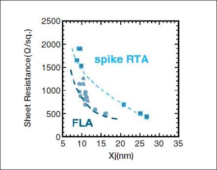
Figure 17. Sheet resistance and junction depth for RTA and FLA.
IV. Insight of the further progress
As stated above, the UV lamps have been changed, improved, and newly invented to match with the requirements derived from the industrial progress in these ten years. To foresee the near future, it is expected that the various other requests will come out from more extensive fields other than the previous ones, and new lighting technologies will be established. 50nm area resolution lighography with near-field light from conventional UV lamps, production method of liquid crystal display by UV light irradiation the UV light irradiation for psoriasis healing and the evaluation for environmental pollution (BTX gasses) by UV light are the parts of the examples. It is predicted that the application of UV light to our life environment and for human’s health will increase gradually, as well as uses in the new industrial fields.
関連製品
論文を探す
光の新しい応用として注目を集めている医療分野、光の周辺技術として重視されつつある検査・測定・シミュレーション分野など、2004年秋から2005年末にかけて発表した論文をご紹介します。
(2006年11月)