Review of Scientific Instruments 76, 086107(2005)
Mechanisms of sound generation during flash lamp operation
Tetsuya Kitagawa,a) Mitsuru Ikeuchi, Yukihiro Morimoto, and Fumihiko Oda
R&D Center, Ushio Inc., 1194 Sazuchi, Bessyo-cho, Himeji, Hyogo-pref. 671-0224, Japan
(Received 14 April 2005; accepted 11 July 2005; published online 9 August 2005)
Changes in sound pressure wave forms by operating flash lamps were studied. In the experiments, two types of lamp were prepared, one of which emitted vacuum ultraviolet(VUV)light and the other did not. We investigated the position of the sound pressure origination, the frequency component, and the relation between the degree of sound pressure and the surrounding atmosphere. It was found that there are two kinds of frequency components in the exploding sound, due to the significant sound pressure. One is an audible frequency component originated from light radiated from the lamp, and the other is the higher frequency component of a nonaudible sound, caused by the mechanical vibration of the flash lamp tube. The audible sound was generated as follows: Oxygen and water vapor absorb VUV light, water vapor absorbs infrared light which is a part of the spectrum of the flash lamp, and heating occurs. Consequently air rapidly expands and generates sound pressure. We propose that sound pressure in operating flash lamps could be strongly reduced by controlling the surrounding atmosphere. © 2005 American Institute of Physics.
[DOI: 10.1063/1.2010431]
Flash lamps produce pulsed radiation, ranges from the vacuum ultraviolet(VUV)to the infrared(IR)light, by electric discharge up to the order of megawatts.1-3 The applications of this lamp are widespread from the strobe for the camera to the emergency lights for the aero systems or as indication lights at night on top of a bridge pier. Moreover, from the viewpoint of industrial applications, flash lamps are utilized as pumping sources for solid-state lasers and heating sources for toner fixing in copying machines and DVD bonding.4,5 Recently the manufacturing process of the semi-conductor has faced a significant turning point in the annealing technology of metal-oxide-semiconductor fieldeffect transistor(MOSFET)with the entering of the 45 nm node, and the flash lamp annealing(FLA) method attracts attention as an annealing technique.6-10 It is because the conventional rapid thermal annealing technology cannot fill the demand to form an ultrashallow junction adjoined source-drain of the MOSFET; that is, FLA is needed to accomplish electrical activation without appreciable thermal diffusion of implanted dopants in the silicon wafers during the process.
In order to achieve the annealing time within a millisecond range over the blanket implanted area, the equipment for the annealing process, with its array of flash lamps which are operated in high input power, has been released. When the flash lamps are operated at high input power simultaneously, an exploding sound, due to the significant sound pressure, is generated, which may cause some problems. An example is the misetting on the semiconductor microfabrication caused by vibration from which harm could be caused to an operator’s body. In the equipment, acoustical materials are employed in the lamp housing, resulting in higher costs.
As long as we have known, research on the sound of lamp has been done only on the resonance effect inside of the lamp, and no research has been done on the generation mechanism of the exploding sound in operation. In this article, sound pressure measurement and frequency analysis in flash lamp operations are reported. We focused attention on the generation mechanism of the audible frequency component originated in the flash light and proposed a sound reduction technique to be used in industrial application.
Figure 1 shows a schematic diagram of the experimental setup to measure the sound pressure in the flash lamp operation. The measurements were performed by operating two flash lamps with different tube materials. One was the“VUV lamp”which radiated a spectrum from the IR to the VUV wavelength, and the other was the O3 free lamp(UFQ-75002P, Ushio Inc.)which radiated a longer wavelength than the VUV light. Both of these lamps were Xe flash lamps of linear shape. They were operated with 0.4 ms pulse duration and 1.4 kJ input energy.
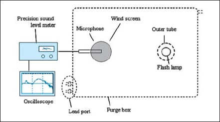
FIG. 1. Schematic diagram of the experimental setup used to measure sound pressure in the flash lamp operation. The outer tube reduces the sound pressure caused by mechanical vibration of the flash lamp tube. A wind screen was used for the purpose of preventing the microphone from exposure to the flash light. The atmosphere in the purge box was changed by controlling the air and nitrogen flow from the lead port through a molecular sieve or water.
In order to avoid the frequency change on the sound source due to lamp fixation, the flash lamp was hung by its lead wires. The sound pressure was detected by the micro-phone(UC-29, RION Inc.)and the wave form was recorded by an oscilloscope(9310A, LeCroy Inc.) through the precision sound level meter(NA-41, RION Inc.)of which the detectable frequency region is 20 Hz-100 kHz.
It has been known that the exploding sound in operating VUV lamps is reduced under a nitrogen atmosphere. We con-sidered that the origin of the sound pressure was caused by radiated light or the mechanical vibration of the lamp tube.
The flash lamp was located in a coaxial outer tube (synthetic silica glass) to reduce the frequency component generated by the mechanical vibration to a negligible level and we measured the sound pressure wave forms by operating the flash lamp. In order to identify the gas species which absorbed light in the air, we investigated the dependence of relative maximum sound pressure in a purge box, where the oxygen concentration and the water vapor were controlled. The sound pressure was measured under the condition of oxygen concentration with 20.5 and 0.06 vol %, while the water vapor pressure was kept at 500 Pa. Later, we measured it with a water vapor pressure of 2400 and 500 Pa, while the oxygen concentration remained at 0.06 vol %.
With respect to the frequency component by the mechanical vibration, we investigated the following:
- (i) the relation between the sound intensity and the distance from the lamp to the microphones; and
- (ii) the relation between the frequency component and the lamp length.
Sound pressure wave forms of the two types of lamp with an outer tube are shown in Fig. 2 for the VUV lamp and the O3 free lamp. A positive value of sound pressure represents the sound propagated with the pressure from the lamp to the detecter. The time, the horizontal axis, indicates the arrival time of the sound to the microphone. The flash lamp was located at 35 cm from the microphone and, in Fig. 2, the horizontal axis, on the top of the graph, corresponds to the distance from the microphone to the sound generating point(sound velocity is assumed to be 340 m/s.)
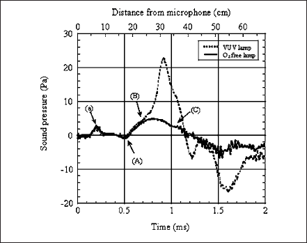
FIG. 2. The sound pressure wave forms in operating the VUV lamp and the O3 free lamp with the outer tube:(A)the origination point of the audible frequency component,(B) the sound pressure wave forms of the VUV lamp and the O3 free lamp differ from this point,(C)a high frequency component superimposes on the wave form after this time, and(a)the point equivalent to the surface position of the wind screen.
In the sound pressure wave form of the O3 free lamp, an audible frequency component of about 600 Hz was generated at point(A), the distance being about 17 cm from the microphone. The higher frequency component was superimposed on the wave form after point(C), which was about 35 cm from the microphone. It is clear that the higher frequency component is caused by the mechanical vibration of the flash lamp tube due to the expansion of the arc column, since the frequency component was generated at exactly the lamp position and was intensified without the outer tube. Moreover the frequency was evaluated to be 27 kHz, a nonaudible sound, by fast Fourier transform analysis. The audible frequency component was generated at a closer position to the microphone than the lamp position with a positive sound pressure. Since light travels faster than sound, it was considered that this frequency component was generated by expanding air which absorbed flash light and heating occurred.
We can see that the sound pressure wave forms of the VUV lamp separate from the 3 free lamp after point(B). This separation seems to be caused by the spectral difference of these two lamps.
At point(a), a small degree of sound pressure occurred. Point(a)is equivalent to the surface position of a wind screen attached to the microphone. Consequently the sound pressure was generated by expanding air within the wind screen.
The sound pressure wave form of the VUV lamp without the outer tube is shown in Fig. 3. The wave form with 400 Pa maximum sound pressure appeared at a few centimeters from the lamp, but this peak could not be observed on the wave form of the O3 free lamp without the outer tube. As the characteristic of the mechanical vibration does not vary with the tube materials of those lamps, it is suggested that some gas species of the larger absorption coefficient were the origin of the audible frequency component with the VUV lamp.
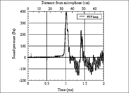
FIG. 3. The sound pressure wave form of the VUV lamp without the outer tube. The significant sound pressure generates near the lamp.
The sound pressure wave forms of the VUV lamp and the O3 free lamp were measured by controlling the oxygen concentration and the water vapor pressure. In the measurement of the O3 free lamp, the lamp was covered with an outer tube to reveal the audible frequency component.
Tables I and II show the dependence of relative maximum sound pressure by the flash lamp operation on oxygen concentration and water vapor pressure, respectively. The sound pressure of the VUV lamp was reduced noticeably with low oxygen concentration, but the sound pressure of the O3 free lamp did not depend on the oxygen concentration.
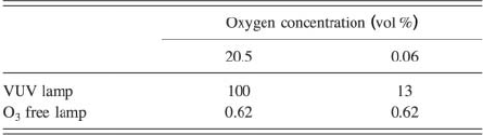
TABLE I. The dependence of sound pressure of the VUV lamp and the O3 free lamp on the oxygen concentration. The water vapor pressure is kept at 500 Pa.
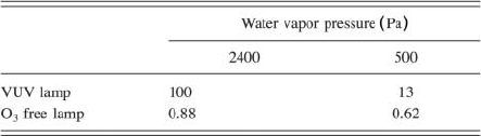
TABLE II. The dependence of sound pressure of the VUV lamp and the O3 free lamp on the water vapor pressure. The oxygen concentration is kept at 0.06 vol %.
The sound pressure of the VUV lamp also was reduced noticeably with low water vapor pressure, and the sound pressure of the O3 free lamp tended to be reduced.
Throughout the experiment we found the following:
- (i) the sound pressure of the VUV lamp was influenced by both oxygen concentration and water vapor pressure and
- (ii) the sound pressure of the O3 free lamp was influenced only by water vapor pressure.
The spectral distributions of the VUV lamp and the O3 free lamp in the UV-VUV region are shown in Fig. 4. The absorption coefficient curve of the atmospheric main constituent: oxygen( O2), water vapor, carbon dioxide, and ozone, which may be reaction products from oxygen, are also shown. Oxygen and water vapor have larger absorption coefficients in the VUV spectrum region.
Negative sound pressure should be caused from volume reduction with ozone formation(3 O2→2 O3)which is an endothermic reaction. But all sound pressure wave forms have positive pressure to the microphone at the beginning. In the VUV lamp, it is certain that oxygen and water vapor absorb the VUV light and cause audible sound pressure by air expansion.
Now, the ozone which was formed may contribute to the sound pressure increase since ozone also absorbs the light in the spectrum region. According to Fig. 4, the O3 free lamp does not emit light below about 220 nm and the absorption coefficients of the atmospheric main constituent are extremely low from this wavelength to the longer side. On the other hand, water vapor has a large absorption coefficient in the near IR region(2.7-2.8µm). The Xe flash lamp also radiated IR light. It is strongly suggested that the audible sound pressure from the O3 free lamp was caused by the water vapor’s absorption of the IR light. According to Fig. 2, the sound pressure wave forms of the VUV lamp and the O3 free lamp coincided in the initial stages. The sound pressure from the VUV lamp was also caused by the water vapor’s absorption of the IR light.
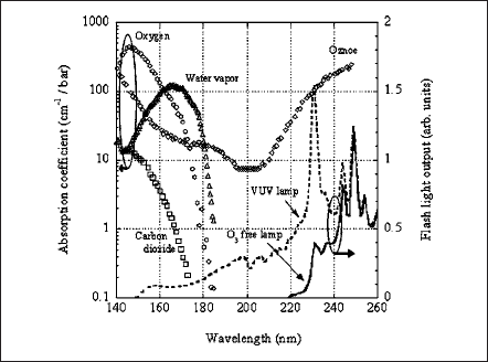
FIG. 4. The absorption coefficient for the oxygen, water vapor, carbon dioxide, and ozone, respectively. The spectral distributions of the VUV lamp and the O3 free lamp are also presented. In the short-wavelength spectral region of the VUV lamp, the atmospheric main constituents have larger absorption coefficients. Data from Ref. 11.
論文を探す
光の新しい応用として注目を集めている医療分野、光の周辺技術として重視されつつある検査・測定・シミュレーション分野など、2004年秋から2005年末にかけて発表した論文をご紹介します。
(2006年11月)