The 18th International Symposium on Plasma Chemistry (ISPC-2005)
Time-dependent modeling of a pulse-current-operated
EUV radiation source
K. C. Paul1, T. Takemura1, G. Niimi2, Y. Teramoto2, H. Sato2, T. Shirai2, K. Bessho2, D. Yamatani2, T. Yokota1,
M. Yoshioka1, T. Igarashi1, K. Hotta1, T. Hiramoto1, and F. Dawson3
1 R&D Center, Lamp Company, Ushio Inc., 1-90 Komakado, Gotenba City, Shizuoka 412-0038, Japan.
2 Extreme Ultraviolet Lithography System Development Association, Hiratsuka R&D Center / Gotenba Branch, Japan.
3 Department of Electrical & Computer Engineering, University of Toronto, Canada.
Since the late 1960’s optical lithography has been an omnipresent engineering system in semiconductor industries for mass-production of integrated circuits (ICs). The incessant advancement of technology has been maintaining the so-called Moore’s law by producing speedy microprocessors, and semiconductor pundits foresee that the semiconductor industries will hold the law true, at least in a coming decade or so. The speed and performance of integrated circuits or of final product, the computer systems, are indeed dictated by the lithographic minimum feature printing capability. In an optical lithographic tool, light of a certain wavelength is the role-player. With the miniaturization of feature size, lithographic system has been required to change for working at shorter wavelength. Today’s state-of-the-art photolithographic tools use deep ultraviolet (DUV) light of 193 nm, which allows printing minimum feature size of 90 nm. There are indications that light of 193 nm may be able to print features as small as 45 nm, and then the conventional optolithography would approach the deadend. Foreseeing this physical limit, semiconductor industries around the globe has put enormous effort to develop new system of lithography, which has been dubbed as next generation lithography (NGL). Among several candidates for NGL, extreme ultraviolet lithography (EUVL) is the most prominent one. In EUVL, extreme ultraviolet (EUV) light of 13.5 nm will be used.
In commercial EUVL system, generation of the EUV light with adequate energy at the intermediate focus (~115 W) is one among many key issues. Plasma of very high temperature is necessary in getting the desired EUV light. There could be two approaches for generating the plasma: either by laser or by discharge. In the today’s R&D stand, discharge produced plasma (DPP) for the EUVL is in the lead. There are several approaches in generating discharge-produced plasma like capillary discharge, hollow-cathode triggered capillary discharge, dense plasma focus and Z-pinch [1].
Mathematical simulation and computer-aided engineering (CAE) have been gaining significant importance in industries because it is an effective tool in expediting new product development and/or improving performance of existing product. It is also seen as a great mean for reducing developing-cost. In the development of reliable and efficient EUV discharge source, modeling is definitely going to play a role. In this paper, we are going to discuss on a newly developed model that can predict the plasma dynamics of an EUV discharge, generated using the capillary and Z-pinch scheme. These predictions are helpful for understanding the source performance, for better design and for increasing source efficiency.
The model solves the time-dependent transport equations of mass, momentum and energy for a compressible fluid. Azimuthal magnetic field compresses the plasma towards the plasma axis and causes the Z-pinch. Curl of Ampere’s law, which is a derivation of Maxwell’s equations, is solved to get the magnetic field. The current density distribution in the plasma is obtained by solving the Laplace’s equation. Solution of current density (J) and magnetic field (B) paves the way to include the Lorentz forces or the JxB terms in the momentum equations. The radiation term in the energy balance equation is introduced using P-1 radiation model [2]. A vendor-supplied CFD (computational fluid dynamics) package, Fluent, is used as the computing platform, where all equations have been solved through customized routines. Figures 1 and 2 illustrate the axi-symmetric geometry and the current profile respectively. A time step of 1 ns has been chosen in the calculations.
For the discharge medium of xenon and a flow-rate of 100 sccm, Fig. 3 depicts the isocontours of temperature in electron-volt (eV) at the time of 137 ns of the current pulse. The maximum temperature at this instant of time has been calculated as about 14 eV. In a comparison of flow-rate effect, it has been seen that hot plasma-core advances along the axial direction with the increase of flow-rate, which is in line with the experimental evidence.
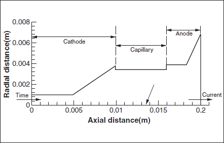
Figure 1. Schematics of the modeled domain of discharge. 2
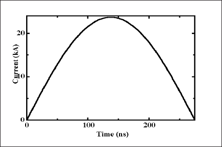
Figure 2. Profile of the supplied current.
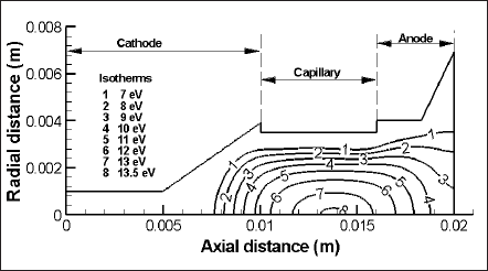
Figure 3. Temperature contours of plasma in eV at time, t =137ns.
関連製品
論文を探す
光の新しい応用として注目を集めている医療分野、光の周辺技術として重視されつつある検査・測定・シミュレーション分野など、2004年秋から2005年末にかけて発表した論文をご紹介します。
(2006年11月)