光技術情報誌「ライトエッジ」No.30(2008年3月発行)
SPIE, 2006 International EUVL Symposium
(2006年2月)
Development of Xe-and Sn-fueled high-power Z-pinch
EUV source aiming at HVM
Yusuke Teramoto*, Gohta Niimi*, Daiki Yamatani*, Yuki Joshima*, Kazunori Bessho*,
Takahiro Shirai*, Tetsu Takemura*, Toshio Yokota*, Hironobu Yabuta*, Khokan C. Paul**,
Kiyoyuki Kabuki*, Koji Miyauchi*, Mitsuru Ikeuchi*, Kazuaki Hotta*, Masaki Yoshioka*
and Hiroto Sato*
* Gotenba Branch, Hiratsuka Research and Development Center,
Extreme Ultraviolet Lithography System Development Association
** Ushio Inc
ABSTRACT
Discharge-produced plasma (DPP) based EUV source is being developed at Gotenba Branch of EUVA Hiratsuka R&D Center. Among the several kinds of discharge scheme, Z-pinch is employed in our source. An all-solid-state magnetic pulse compression (MPC) generator is used to create a Z-pinch plasma. Low inductance MPC generator is capable of producing a pulsed current with over 50kA of peak amplitude and about 100ns of pulse duration at 7kHz of pulse repetition frequency. In order to obtain sufficient output radiation power, tin-containing gas is being used as well as xenon. Due to the high spectral efficiency of tin, demonstrated EUV output power reached 645W/2πsr within 2% bandwidth around 13.5nm. A novel scheme of fuel gas supply led to as good output energy stability as xenon can achieve. Using a nested grazing-incidence collector, EUV power at intermediate focus point which is defined as an interface to the exposure tool reached 42W with 3.3mm2 sr of etendue.
Keywords : DPP, EUV source, lithography, xenon, tin, Z-pinch, pulsed power
1. INTRODUCTION
EUV is expected as a light source used in the next generation lithography. In order to match the requirements1 for high-volume-manufacturing (HVM) tools , EUV source must solve many issues such as power, optical quality, lifetime and cleanliness. Comparing with a laser-produced plasma (LPP) source, DPP source has the worthy advantage in terms of its direct conversion from electrical energy to photon energy. On the other hand, largest disadvantage of the DPP source may be debris production that is caused by erosion of the electrode and dielectric surfaces. Because debris easily damages EUV optics, the development should be conducted to increase the EUV power with minimizing or mitigating debris.
Although several schemes are available to create a high energy-density plasma such as dense plasma focus (DPF)2, hollow-cathode-triggered Z-pinch (HCT-Z)3, capillary discharge4 and Z-pinch5-6, our developing source employs Z-pinch from the viewpoint of its simplicity and thermal resistance. Capillary discharge can keep the high temperature plasma during relatively long time because the small-diameter capillary (dielectric tube) is used, and relatively low-amplitude and long-duration current pulse drives the load. Conventional Z-pinch plasma is created in a large-diameter dielec tric tube or vacuum. Large current pulse creates the azimuthal magnetic field around the cylindrical initial plasma or gas, and magnetic pressure compresses the plasma toward the central Z-axis7 . Capillary discharge is good in terms of stability, however Z-pinch is better in terms of radiation brightness and lifetime of dielectric wall. When the source is used in a HVM tool, it must operate at least 7kHz1 and in quasi-continuous mode. Conversion efficiency from electrical input to inband (λ=13.5nm, 2% bandwidth) radiation is on the order of, at most, a few percent. Therefore thermal input into the proximity of electrodes becomes huge. Also high energy-density plasma emits thermal or highspeed particles. In order for the source to have sufficient resistance to such inputs, plasma must be isolated from the surrounding parts with significant distance. Zpinch seems to have such properties that fulfill above demands. Output EUV power is determined by a function of input power and conversion efficiency. In order to obtain sufficient output power from reasonable input power, it is very important to increase conversion efficiency. There likely to be three major ways to increase conversion efficiency; geometry of the discharge region, shape of the drive current, and choice of fuel material. Fuel material is an essential part among them to determine conversion efficiency. In previous works, most research and development were carried out with xenon. Xenon has fascinating material in terms of cleanliness. However, tin is also fascinating material because it is able to maximize conversion efficiency of 13.5nm radiation. In pioneer researches, high conversion efficiency of 13.5nm was demonstrated on the basis of that 4d-4f resonance line transition is located at 13.5nm8. On the other hand, it has not been preferred due to the handling difficulty. Recently, novel scheme of tin supply has been developed. Although protection of collector optics from the metal debris must be solved, tin-fueled DPP would be a potential candidate for HVM-enabling EUV source. In this paper, latest update of our source development is described. By using Z-pinch source head, high-repetition-rate pulsed power driver and EUV metrology tools9, xenon- and tin-fueled sources are evaluated. This paper is dedicated to describe xenon-fueled source performance and improvement of source performance by tin. Other topics related to this development will be described in Ref.10.
2. DISCHARGE HEAD AND POWER SUPPLY
Fig.1 shows conceptual cross section of the discharge head. The head basically consists of a set of anode, insulator and cathode. A coaxial conductor feeds the pulsed electrical energy from the generator into the head. Both electrodes are cooled by circulated water. The source head was designed to minimize the circuit inductance, maximize collection angle of EUV radiation, and increase thermal resistance from the electrical current and the plasma. As already known, EUV radiation is collected by a collector and focused on the intermediate focus (IF), which is an interface between the source and exposure tool. EUV source is required to obtain sufficient EUV power at IF. IF power is determined by the radiation power from the plasma (source power), absorption by gases and debris shields, and collection efficiency. Collection efficiency is a function of collector performance and plasma shape11.
Fig.2 shows a circuit diagram of the power supply (magnetic pulse compression generator, MPC). Intermediate compression stages of the MPC generator are not shown in this figure. The final capacitor of 133nF is charged to 14.5kV (rated voltage), which equals to 14 J of electrical energy storage. The generator system was modified in order for better coupling between the generator and load. Currently the generator system is capable of providing >50kA of peak current with ~100ns of pulse duration. Improved generator performance increased EUV output power effectively, which was mainly due to the decrease of output inductance. The all-solid-state MPC generator allows very stable operation at up to 7kHz. Pulse-to-pulse stability of output current was 2.1% (3б) achieved at 7kHz.
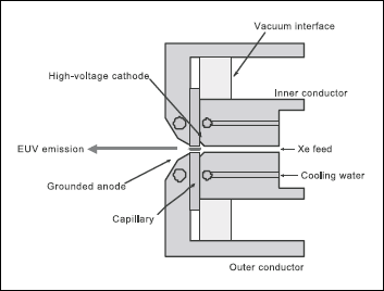
Fig.1. Schematic cross section of the discharge head.
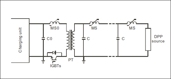
Fig. 2. Circuit diagram of the MPC generator. Intermediate stages are not shown.
3. XE-FUELED SOURCE PERFORMANCE
3.1 Basic performance
Fig.3 shows dissipated energy, in-band radiated energy, and conversion efficiency as a function of gas flow rate. Each point represents averaged data. At the optimum condition, highest EUV energy of 6.7 mJ/sr/2%BW was obtained. Z-pinch plasma is created due to the inward compression by the magnetic pressure. In Xe plasma, in-band EUV (λ=13.5nm) emission is radiated only by Xe10+ ions of which the fraction depends on the plasma temperature and density. Fig.3 showed that variation of initial density (flow rate) resulted in the variation of plasma parameter and resultant fraction of Xe10+ ions for given power supply and electrode geometry.
Conversion efficiency (CE) is also very important point because it determines the necessary capacity of pulsed power generator and thermal sink of the discharge head. CE was calculated by the following equation.
where EEUV, Einput, V0, V1 are on-axis in-band energy per unit solid angle, electrical energy input, initial capacitor voltage and capacitor voltage reversal after the current pulse, respectively. In this equation, uniform radiation into half spherical volume is assumed. Energy input is based on capacitor energy, and includes ohmic and magnetic energy loss between the capacitor and discharge head. Note that intrinsic CE determined by dissipated energy in the discharge head is much higher than the value calculated here. Gas absorption is not considered here.
Fig.4 shows pulse and dose energy integrated over 50pulses measured at 7kHz. Since higher flow rate described above was used, first several pulses do not have enough energy. However, the energy rapidly reached average level, then remained stable. There are possible reasons to make energy stability worse, for example, gas dynamics, MHD instability during implosion phase, inhomogeneity of initial plasma fill. In our research, we employed increased gas flow, short current duration and large current amplitude, active preionizing to eliminate the seed of energy instability mentioned above. At this moment, 4.3mJ/sr/2%BW/pulse was obtained even at 7 kHz. It equals to the source power of 189 W/2%BW into 2πsr. Having the source power and shape of the plasma, IF power reached 19W/2%BW.
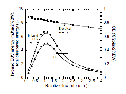
Fig.3. Total dissipated electrical energy, in-band EUV energy and conversion efficiency as a function of Xe flow rate.
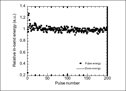
Fig.4. Pulse and integrated EUV energy over 50 pulses measured in 7-kHz discharge.
3.2 Out-of-band radiation
EUV source is not a coherent source so that the radiation of very wide wavelength region from X-ray through infrared can be emitted. It is required for lithography sources to suppress out-of-band (OoB) radiation energy to certain level1. In order to know the contribution of OoB radiation, energy measurement and plasma observation were carried out using different spectral filters.
Table 1 shows the result of OoB energy measurement. Calorimeter was placed at IF point and energies of each wavelength region were measured by changing a filter in front of the detector. It is very interesting that most radiation energy is in the wavelength region of <120nm. This result was well explained by the plasma average temperature. Z-pinch plasma is changing its density and temperature in time. However, temperature averaged over a discharge period (several hundreds of ns toµs) would be on the order of tens of eV. Such a plasma emits radiation of mostly less than 130nm as derived by Planck's equation.
When compared with in-band energy, contribution of OoB, especially UV, is larger than the requirement. Therefore OoB energy must be reduced or suppressed by some means. Fortunately, EUV source employs a collector to deliver the EUV radiation to the exposure tool. Collection efficiency highly depends on the shape of the plasma. In other words, different shapes result in different powers at IF point. Discharge-produced plasma varies its density and temperature during the period. Thus it had been expected that the shape of the plasma also changes in time. In order to confirm a hypothesis , picture of the plasma was taken by a filtered pinhole camera.
Fig.5 shows the pinhole pictures of two different wavelengths. It is obvious that OoB-emitting region is much larger than in-band region. Therefore, large part of the OoB radiation cannot be focused on IF point and cannot be delivered to the exposure tool. It was understood that collectors play additional role as an OoB filter which helps us realize the EUV source that completely fulfill the requirements.
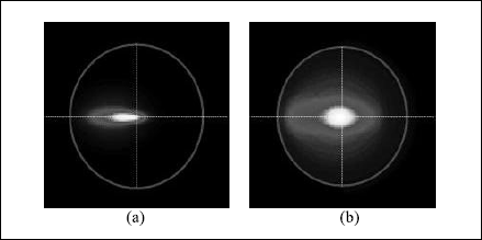
Fig.5. Picture of the plasma emitting radiation of EUV (a) and λ>120 nm (b) taken by a filtered pinhole camera.
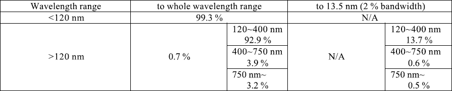
Table1. Out-of-band contribution in the radiation energy
4. SN-FUELED SOURCE PERFORMANCE
4.1 Tin delivery
State of the compressed high energy-density plasma by Z-pinch effect depends on the electrode geometry, gas condition and shape (amplitude and duration) of the drive current. Therefore it is very important to control the gas condition (pressure and flow rate) for controlling radiation condition. Tin is a solid metal at standard condition (room temperature, 1 atm). Therefore conventional method employs heating or laser irradiation or particle (neutral, ion and electron) impact to create tin gas by means of vaporization. However, it seems difficult to utilize such methods in terms of vapor pressure control. Most effective method is to use a kind of tin vapor and control its flow rate by a commonly-used mass-flow controller (MFC). Additionally, such a tincontaining vapor should be at gaseous state at reasonable temperature and pressure. It was found that tin hydride (SnH4, stannane) fulfills such demands. Stannane has similar molecular weight to xenon, and boiling temperature of -52°C. Its flow is controlled by a MFC like xenon gas. Moreover, it is tin combined with hydrogen. Once discharge occurs, stannane is dissociated into tin and hydrogen. However, hydrogen is the lightest atom so that hydrogen does not cause significant radiation loss that occurs with heavy (high-atomicnumber) atoms. Fig.6 shows an example of the result of pressure control of stannane. The pressure was successfully controlled by changing flow rate and showed very similar tendency to xenon. The result said that stannane is stably delivered to the discharge region and its flow rate is well controlled by MFC.
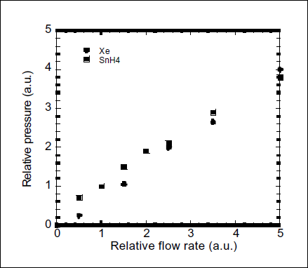
Fig.6. Pressure dependence on the flow rate for xenon and stannane.
4.2 Stannane-fueled discharge demonstration
For the demonstration of high CE of tin, EUV energy and spectrum were measured. Fig.7 shows the comparison of in- band EUV energy (a) and spectrum (b), respectively. Note that the spike seen in the spectrum at wavelength of about 12.4nm is a calculation error. Spectrum was measured with a transmission-grating spectrometer in which the grating is made of silicon nitride. Thus the absorption edge of silicon appeared in the spectrum, which resulted in the spike when the diffraction efficiency was numerically corrected. It is clearly understood, from Fig.7, that stannane-fueled Z-pinch improved CE by a factor of 2.8 than xenon. This high CE is explained by high spectral efficiency (in-band domination in the emission spectrum) seen in Fig.7(b). As described in 3.1, xenon-fueled Z-pinch obtained sufficient radiation stability. Although the radiation energy can be adjusted by means of feedback control, certain level of stability must be obtained even without feedback. Pulsed power generator provides excellent output stability. Therefore gas flow condition and plasma hydrodynamics are essential for the radiation stability.
Fig.8 shows an example of EUV signal measured at 1 kHz on stannane-fueled Z-pinch source. Due to wellcontrolled stannane flow, as sufficient rediation stability as xenon-fueled source was obtained even at high pulse repetition rate.
Finally, output power linearity up to 5kHz was experimentally demonstrated. Fig.9 shows the output in-band power as a function of pulse repetition rate. Even in the high repetition rate discharge, higher CE was confirmed from 1000 through 5000Hz. Moreover,CE measured in this experiment (~1.7) was 30% higher than that for low repetition rate (~1.3%). CE at repetition rate of 4000 and 5000Hz, in Fig.9, is a little less than a linear line of CE 1.7%. This would be caused by flow rate limitation. In this experiment, measurements were done with fixed stannane flow rate. Therefore, if flow rate is increased to sufficient value, output power should follow the linear line that may be determined by discharge condition. At 5kHz, in-band output power reached 645 W/2πsr/2%BW.
Fig. 10 shows the picture of in-band-emitting tin plasma taken by an in-band pinhole camera with 200pulses of exposure. Because the shape of the plasma was not optimized at the time of the experiment, in -band radiation emitted from a relatively large surface of the plasma. However, owing to the good performance of the discharge head and tin delivery, the shape is still good although it is a time -integrated picture. Having this plasma picture, collector performance and absorption by gas and debris -shield, it was derived that IF power reached 42W into 3.3mm2 sr.
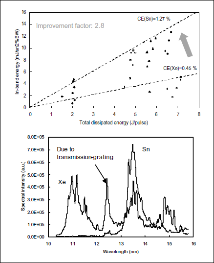
Fig.7. In-band EUV energy (a) and spectrum (b) measured using stannane. Those for xenon are also shown for comparison.
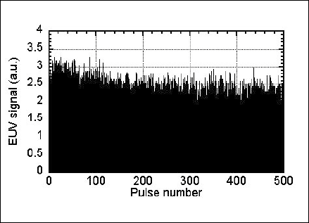
Fig.8. EUV signal measured in 1-kHz discharge with stannane as fuel gas.
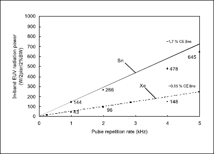
Fig.9. In-band radiation power from source plasma measured with xenon and stannane.
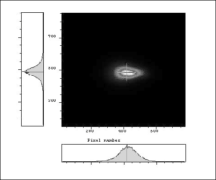
Fig.10. Time-integrated picture of in-band radiation emitted from stannane plasma, taken by a pinhole camera exposed over 200 pulses.
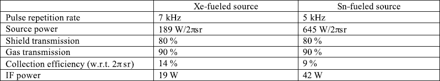
Table 2. Comparison of DPP source performances
5. CONCLUSION
Latest update of the xenon- and tin (stannane)-fueled DPP source performances were described. Achievements are summarized in Table 2. Xenon-fueled source achieved 19W of IF power. Out-of-band radiation was investigated in the xenon-fueled source. Entire spectral distribution was understood, and its contribution to the radiation power focused on IF was addressed. OoB radiation may not be a significant issue in DPP source. Tin-fueled source achieved 42W of IF power using stannane gas as a tin delivery. Because of adequate properties of stannane, very high CE and output energy stability were confirmed. The result would support the feasibility of tin-fueled DPP EUV source in HVM source. IF
関連製品
論文を探す
![ライトエッジ No.30 [特集号] EUV光源](./content_file/file/lightedge_30.png?_size=1)
次世代半導体の実現に向けて、今、最も可能性が高く、大きな期待が寄せられている「EUV露光技術」にスポットをあて、その核となる「EUV光源」の技術論文を編集したEUV特集号です。
(2008年03月)