光技術情報誌「ライトエッジ」No.30(2008年3月発行)
SPIE, 2007 International EUVL Symposium
(2007年2月)
Development of Sn-fueled high-power DPP EUV source
for enabling HVM
Yusuke Teramoto, Zenzo Narihiro, Daiki Yamatani, Takuma Yokoyama, Kazunori Bessho,
Yuki Joshima, Takahiro Shirai, Shinsuke Mouri, Takahiro Inoue, Hiroshi Mizokoshi,
Gohta Niimi*, Tomonao Hosokai*, Hironobu Yabuta, Kohkan C. Paul, Tetsu Takemura,
Toshio Yokota, Kiyoyuki Kabuki, Koji Miyauchi, Kazuaki Hotta, and Hiroto Sato
Gotenba Branch, Hiratsuka Research and Development Center,
Extreme Ultraviolet Lithography System Development Association
* Ushio Inc.
ABSTRACT
Discharge-produced plasma (DPP)-based EUV source is being developed at Gotenba Branch of EUVA Hiratsuka R&D Center. A high-repetition-rate high voltage power supply (HVPS) was developed and put into operation on the magnetic pulse compression (MPC)-driven DPP source, enabling 8-kHz operation with 15 J/pulse of maximum charging energy and 0.11% of stability. SnH4 gas was used as a fuel gas in order to obtain high conversion efficiency. SnH4-fueled Zpinch source demonstrated EUV power of 700W/2πsr within 2% bandwidth around 13.5nm. Using a nested grazingincidence collector, EUV power at the intermediate focus which is defined as an interface to the exposure tool reached 62W with 3.3mm2 sr of etendue. Tin deposition rate on the collector surface, which is the concern in any tin-fueled EUV sources, was decreased by four orders of magnitude as a result of debris-shield development. Cleaning processes were also developed to enhance total lifetime of the collector. A sequence of intentional deposition and cleaning process for the ruthenium grazing-incidence mirror sample was repeated 13 times. By measuring reflectivity of the mirror, it was confirmed that halogen cleaning process worked very effectively and did not get the mirror damaged after such a long-term cleaning experiment.
Keywords : EUV source, Xe, Sn, Z-pinch, discharge-produced plasma
1. INTRODUCTION
EUV is expected as a light source used in the next generation lithography to ensure small feature size of semiconductor. In order to fulfill the requirements1 for highvolume-manufacturing (HVM) tools, EUV source must solve many issues such as power, optical quality, lifetime and cleanliness. Comparing with laser-produced plasma (LPP) sources, DPP sources have worthy advantage in terms of its direct conversion from electrical energy to photon energy. On the other hand, disadvantage of the DPP source may be debris production that is caused by erosion of the electrodes. Because debris easily damages EUV optics, the development should be conducted to increase the EUV power with minimizing or mitigating debris.
Recently, tin is being used as a fuel material that can more efficiently radiate 13.5nm than xenon. Therefore, debris related to the fuel choice became more important than that related to the component erosion. Protection of the collector optics against the debris is, now, of great importance in EUV source development for either DPP or LPP.
Although several schemes are available to create a high energy-density plasma such as dense plasma focus (DPF)2, hollow-cathode-triggered Z-pinch (HCT-Z)3,capillary discharge4 and Z-pinch5-6 , our developing source employs Z-pinch from the viewpoint of its simplicity and thermal resistance. Capillary discharge can keep the high temperature plasma during relatively long time because the small-diameter capillary (dielectric tube) is used, and relatively low-amplitude and long-duration current pulse drives the load. Conventional Z-pinch plasma is created in a large-diameter dielectric tube or vacuum. Large current pulse creates the azimuthal magnetic field around the cylindrical initial plasma or gas, and magnetic pressure compresses the plasma toward the central Z-axis7 . Capillary discharge is good in terms of stability, however Z-pinch is better in terms of radiation brightness and lifetime of dielectric wall. When the source is used in a HVM tool, it must operate at least 7kHz1 and in quasi-continuous mode. Conversion efficiency from electrical input to inband (λ=13.5nm, 2% bandwidth) radiation is on the order of, at most, a few percent. Therefore thermal input into the proximity of electrodes becomes huge. Also high energy-density plasma emits thermal or highspeed particles. In order for the source to have sufficient resistance to such inputs, plasma must be isolated from the surrounding parts with significant distance. Zpinch seems to have such properties that fulfill above demands.
In recent years, some DPP sources employ disk-type electrodes which have uniform surface and are rotating to increase equivalent surface area. This so-called rotating-disk electrode (RDE) source allows significant thermal power input and accept larger sputtered amount of the electrode material. Consequently higher output power and longer lifetime are expected on RDE sources.
Output EUV power is determined by a function of input power and conversion efficiency. In order to obtain sufficient output power from reasonable input power, it is very important to increase conversion efficiency. There likely to be three major ways to increase conversion efficiency; geometry of the discharge region, shape of the drive current, and choice of the fuel material. Fuel material is an essential part among them to determine conversion efficiency. In previous works, most research and development were carried out with xenon. Xenon is fascinating material in terms of cleanliness. However, tin is better material because it is able to maximize conversion efficiency of 13.5nm radiation. In pioneer researches, high conversion efficiency of 13.5nm was demonstrated on the basis of that 4d-4f transition is located at 13.5nm8 . On the other hand, it has not been preferred due to the handling difficulty and debris production.
Although protection of collector optics from the metal debris must be solved, tin-fueled DPP would be a potential candidate for HVM-enabling EUV source. We are doing research and development of DPP source utilizing SnH4 gas as a fuel material. SnH4 is a gas and therefore can be easily handled like when we use xenon. In this paper, latest update of our source development is described. By using Z-pinch source head, high-repetition-rate pulsed power driver and EUV metrology tools9 , SnH4-fueled source is evaluated. Not only the power, collector lifetime issues are discussed as well.
2. PULSED POWER DRIVER
Fig.1 shows the diagram of a version of pulsed power driver used in the experiment. It consists of a rapidcharging high-voltage power supply (HVPS), energy storage capacitors, IGBT switches and magnetic switches. The HVPS charges a primary storage capacitor (CO) up to several thousands of volts which can be handled by general IGBTs. When charging has completed, IGBTs are triggered to transfer the energy to the following capacitors. A scheme for increasing voltage to an appropriate value, such as a pulse transformer, is placed somewhere between CO and the load. A magnetic switch is a kind of passive switch in which ferromagnetic cores and windings are used to form a saturable inductor. It can stand very wide range of voltage and conduct very large current. By connecting a combination of capacitors and magnetic switches in series, with each inductance becoming lower than the previous stage, the electrical pulse can be compressed. Final shape of the electrical pulse, normally which appears as a current pulse, becomes half sinusoidal with amplitude of several to tens of kA depending on the load impedance.
As commonly known, EUV sources must work at more than 7kHz of repetition rate. One of the important points in making a pulsed power driver is charging time. For example, 10kHz gives us just 100µs between each pulse. Within such a short period, charging, switching, pulse compression, discharge, and in some cases energy recovery as well must be completed. In addition, in an actual EUV source employed in a lithography tool, a feedback energy-stability control system must be equipped in the source. Time reserved for data transfer and calculation is no more negligible. Therefore, charging time must be more shortened than as repetition rate increases. In order to realize such a high-frequency operation, a high-power rapid-charging HVPS was built and put into operation in the experimental facility. Fig.2 shows the voltage waveform measured at the primary capacitor, which is connected to the HVPS. As seen in the waveform, each sequence of charge and discharge completed within 125µs to enable the entire system work at 8kHz. Moreover, it is clearly seen that the initial voltage was not zero but started from a certain value. It is because the system is equipped with the energy recovery system. The energy recovery system absorbs backward electrical energy that is not deposited in the discharge, and reuses it in the subsequent pulse to improve the overall efficiency. An up-to-date HVPS, named G6, is capable of 8-kHz operation at 75% of duty cycle and 6-kHz continuous operation with 15J/pulse of charge energy. Output voltage can be externally controlled in each pulse, to work with a feedback control system. Pulse-to-pulse voltage stability obtained with this HVPS was 0.11%
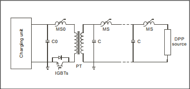
Fig.1. Conceptual diagram of a version of high-power, high-repetition-rate pulsed power driver.
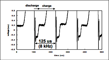
Fig.2. Typical waveform of output voltage of the 8-kHz HVPS.
3. TIN-FUELED DPP SOURCE CHARACTERIZATION
In order to achieve as high conversion efficiency as possible, it is necessary to use tin as a fuel material as well as to optimize the plasma parameter. Tin is considered to show several times higher conversion efficiency than xenon that has been used in previous works. However, the difficulty of using tin as a fuel material is in its handing and collector protection against the deposition of tin. Although there has been several approaches took place in other researches, our interest is to use gaseous state of tin. In case of Z-pinch, implosion occurs as a result of pressure balance between internal gas pressure and external magnetic pressure. Thus changing gas pressure, more exactly saying gas flow rate fed into the discharge region, is essential for optimizing plasma parameter under the given condition. It is reasonable to use gaseous tin instead of solid or molten tin to enhance the conversion efficiency over the value obtained ever with xenon. One solution to feed tin into the discharge region, which is placed in the vacuum chamber, is utilization of tin hydride (SnH4). SnH4 is a gas at room temperature and able to be controlled by a mass-flow controller. In our previous works, it was confirmed that the flow of SnH4 could be controlled just as same as xenon and approximately 3-fold higher conversion efficiency could be achieved than xenon.
Having the fact proven in previous works, further research and development are being continued pursuing both higher EUV power at the intermediate focus and sufficient lifetime of the source components. A critical issue for gas-discharge sources seems to be erosion of the electrodes due to huge amount of heat, particle and radiation fluxes. Therefore, recent research is mainly dedicated to make long-life-time electrode system under the condition of high-repetition-rate and high-power input. Fig.3 shows a schematic cross section of the discharge head. It is attached to the pulsed power driver in order to minimize load inductance, which leads to maximization of load current amplitude with the given voltage.
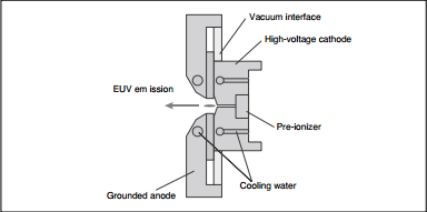
Fig.3. Schematic cross section of the discharge head.
The electrodes are placed in vacuum, and isolated each other to form grounded anode and high-voltage cathode. Fuel gas, here which is SnH4, is fed and pre-ionized prior to the main discharge. Such pre-ionization creates weakly-ionized gas between the electrodes, where main current pulse causes Z-pinch implosion to compress the plasma to have sufficiently high density and temperature for EUV radiation. Pre-ionization is considered to be necessary for obtaining better radiation energy stability. Both electrodes are designed not to be damaged thermally, and cooled by water.
Fig.4 shows the screen copy of the oscilloscope showing in-band radiation signal measured in subsequent 200 pulses at 6kHz(a) and 8kHz (b), respectively. It was found from the experiment that some pulses were lower than other pulses or even missed. The reason of this misfire might be insufficient stability of feed gas. In case of 8kHz, time interval between pulses is just 125µs. It is preferred for discharge that all pulses have equal condition. Shorter pulse interval does not give enough time to the discharge region for recovering the initial, in other word, demanded condition. In addition, from the viewpoint of pulsed power driver, it becomes hard to reset the magnetic switches in the compression stages. It is remarkable that SnH4 was stably fed into the discharge head supplying almost all amount of necessary tin at 8 kHz of discharge frequency. Here, pulseto- pulse and 50-pulse-dose stability of in-band energy were 10.7% and 2.4% for 6kHz, and 15.7% and 2.4% for 8kHz, respectively.
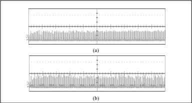
Fig.4. In-band radiation pulses measured in 6-kHz (a) and 8-kHz (b) discharges. Subsequent 200 pulses are shown in these waveforms.
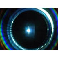
Fig.5 shows frequency dependence of in-band radi-ation power. Each data points show the results obtained under optimized condition. It is very interesting to find that the tendency is not linear over the frequency. As frequency increased, in-band radiation power increased more than increase of frequency. This is because the electrodes used in the experiment were specially designed for high-frequency discharge. At 8kHz, 700 W/2πsr of inband radiation power was achieved so far. Fig.6 shows the picture of the plasma taken by an in-band pinhole camera at the condition of 700-W radiation power. Note that the picture is a time-integrated one in which 50pulses were exposed. Even though spatial instability of the plasma might have appeared in this superimposed picture, the diameter and length of the plasma was 0.75mm and 4.6mm, respectively. Fig.7 shows the ray-tracing result to show the usable power at the intermediate focus for an assembly of the debrisshield and the nested grazing-incidence collector. In this calculation, 62W of in-band power was achieved for etendue of 3.3mm2 sr with 702W/2πsr of source power at 8kHz operation. Detailed present performance including transmission and collection efficiency is shown in Table 1. Note that collection efficiency strongly depends on the plasma size10 and the design of collector. In this case, the plasma size was not optimized yet that higher power is anticipated when we make itsmaller.
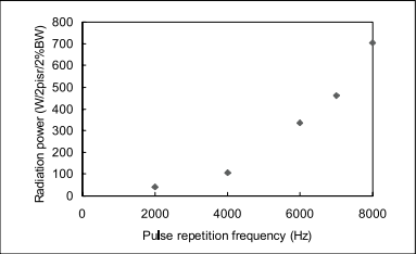
Fig.5. Dependence of in-band radiation power on pulse repetition frequency.
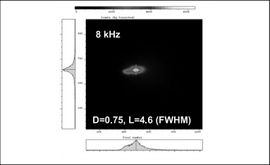
Fig.6. In-band emission image taken by a pinhole camera during 8-kHz burst discharge.
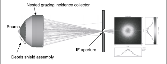
Fig.7. Ray-tracing result for the calculation of radiation power at the intermediate focus.
Table 1. Summary of the latest results in terms of power.
Not only the power but also the lifetime of the source components such as electrodes, debris shield and collector is important standpoint to assess the source performance in terms of commercialization. Collector lifetime will be described later. Because large amount of energetic ions are emitted from the plasma when Zpinch collapses, the surface of surrounding electrodes can be sputtered away. Sputtering may result in the change of electrode shape or inter-electrode distance with increasing accumulated number of pulse. It leads to decoupling of pulsed power driver and load (plasma), change of gas density distribution, or change of plasma shape. Especially in case of xenon-fueled source, sput-tering of the electrode is significant and essential for the lifetime limit. However, SnH4-fueled source could have less electrode sputtering because it contains hydrogen, a lightest atom. Light ions are accelerated faster than heavy fuel ions such as xenon or tin, and relief the electric field creased by the electrons which are expanded first when the plasma collapses12. Therefore, SnH4-fueled source would have prospect of better performance in terms of lifetime.
Fig.8 shows variation of in-band radiation energy measured during an 8-kHz long-term discharge. Duty cycle was decreased to 6.25%, and feedback control was not used. SnH4-fuelded discharge was maintained for approximately 10minutes showing no power degradation. It is now being pursued to operate the source with higher average power load by increasing duty cycle to, ultimately, 100%.
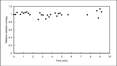
Fig.8. Relative in-band radiation energy measured during an 8-kHz long-term discharge run.
4. COLLECTOR PROTECTION AND CLEANING ON TIN-FUELED DPP SOURCE
The most challenging technical issue seems to be the protection of collector against the debris because tin is condensable material and can be deposited on the collector surface. Reflectivity of a grazing incidence collector strongly depends on surface roughness and thickness of deposited tin. Therefore, neutral atoms and particles must be prevented from entering the collector as well as fast ions. Here the characterization of debris from SnH4 plasma and development of debris-shield system were carried out.
In the experiment to figure out how tin debris affect the collector surface, two test samples of silicon-substrate ruthenium mirror were placed on the axis of the discharge, and 15-degree off axis. After 0.25Mpulses of SnH4 discharge exposure at 1kHz without using any debris-shield, those samples were observed by means of secondary ionization mass spectrometer (SIMS). Fig.9 shows depth profiles of on-axis(a) and off-axis(b) samples, respectively. The thickness of deposited tin was approximately 100nm(a) and 10nm(b). In addition, mixture of ruthenium and tin appeared near the surface of the mirror. It must be because fast ions were deeply impacted into the sample, just as same as seen in the previous xenon-fueled source experiment. It implied that many fraction of debris came from the plasma as fast ions. It was thought, therefore, that a kind of foiltrap could work effectively to stop these fast ions. Fig.10 shows deposition thickness of tin measured by a quartz crystal microbalance (QCM) as a function of accumulated pulse number of the discharge. In the experiment, ruthenium-coated QCM was placed in the grazing incidence of the exposure angle to simulate an actual collector geometry. QCM was exposed in several sets of experimental run, in which 1kHz continuous discharge took place for 10s. Without any debris mitigation, deposition rate was 3.9×10⁻⁴ nm/pulse. Just using foiltrap decreased deposition rate to 1.0× 10⁻⁶ nm/pulse. In order to enhance effectiveness of the foiltrap, gas flow in the DPP source system was controlled. As a result, 3.2×10⁻⁸ nm/pulse of deposition rate was achieved. Debris affecting the collector has been mitigated by 4orders of magnitude so far. Although it is preferred to improve the effectiveness of the debris shield, cleaning system described below would fulfill the lifetime requirement.
In case of xenon-fueled source, no significant fuel-related contamination of the collector is expected. In stead, if mitigation is not sufficient, debris (fast ions) sputter the surface to make unrecoverable damage to the collector. In case of tin-fueled source, on the other hand, even though the mitigation is not sufficient and contamination occurs, damage can be cured by a cleaning process. Media which are chemically or physically react with tin, such as hydrogen radical or halogens, can be used for the cleaning. Fig.11 shows a result of cleaning experiment using halogen gas. The experiment was carried out using Ru mirror sample, SnH4 as contamination medium and a halogen gas as cleaning medium. The mirror sample was placed at grazing angle on the virtual surface of the real collector. After both exposure and cleaning process, EUV reflectivity was measured to evaluate cleaning effectiveness. After intentional decrease in reflectivity by 0.1~0.2%, the mirror sample was treated by a halogen gas. Thirteen sets of experimental run showed sufficient recovery of the reflectivity in every process, which is due to the removal of tin layer. Moreover, there was no sign of reflectivity degradation appeared even after thirteen processes. Therefore, it does not mean the collector lifetime is limited by the number of cleaning processes. It can be said, so far, that halogen cleaning process is enough usable and capable of renewing the mirror surface at higher cleaning rate than hydrogen radical of which we confirmed effectiveness.
However, it is important that we should choose better solution for the actual collector setup in terms of effectiveness, safeness and compatibility to the source system.
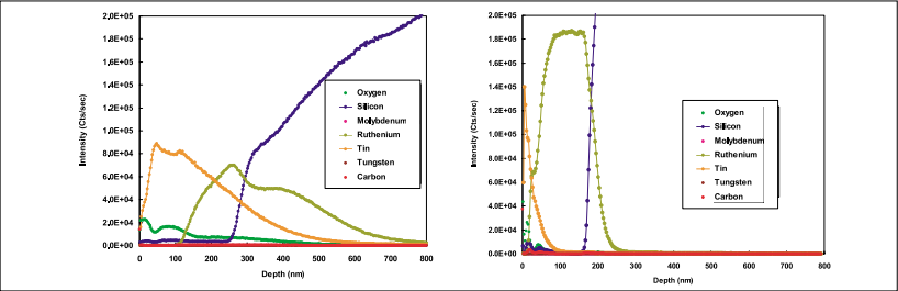
Fig.9. Depth profiles of Ru sample exposed by SnH4-discharge without using debris shield, placed on the axis(a) and 15°off-axis(b).
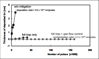
Fig.10. Thickness of deposited tin measured by QCM under three different conditions; without mitigation, with foiltrap only, and with foiltrap and gas flow control.
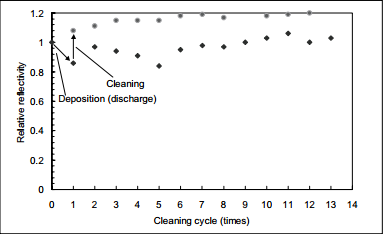
Fig.11. Result of repeated cleaning test using halogen gas. Upper and lower dots are reflectivity before and after the cleaning, respepctively.
5. CONCLUSION
Latest update of the SnH4-fueled DPP source performances were described. The pulsed power driver successfully demonstrated 8-kHz discharge operation. Inband radiation power obtained in 8-kHz discharge reached 700W/2πsr, and the power at intermediate focus reached 62W. Debris shield development achieved four orders of magnitude of mitigation with 3.2×10⁻⁸nm/pulse of deposition rate. Halogen cleaning of contaminated Ru mirror showed significant effectiveness of reflectivity recovery without any undesirable degradation of mirror performance over 13 repetitive processes.
The result would support the feasibility of tin-fueled DPP EUV source in HVM source. IF power achieved now is close to the half of the requirement for HVM. It can be believed that HVM-level output power can be obtained with tin-fueled DPP by further modification of plasma shape, pulse repetition rate and pulse input energy. Debris-related issue and component lifetime issue, which are still necessary to be researched further, are of course concerns. Together with the research and development of each component, consideration and actual evaluation of entire source system from the discharge to IF will be took place as a future work.
関連製品
論文を探す
![ライトエッジ No.30 [特集号] EUV光源](./content_file/file/lightedge_30.png?_size=1)
次世代半導体の実現に向けて、今、最も可能性が高く、大きな期待が寄せられている「EUV露光技術」にスポットをあて、その核となる「EUV光源」の技術論文を編集したEUV特集号です。
(2008年03月)